Installation and commissioning
[19]
• Install measuring cables according to general standards for measuring and control
cables.
• If possible, install cables in metallic cable channels or tubes.
• Observe that the measuring cables are arranged orthogonally.
5.3.1 Connections and wiring
The EZ 1000 is equipped with four screw terminals for power supply connection and
output signal connection, and a LEMO socket for the connection of one eddy current
sensor. See
Table 5-1
for the minimum and maximum permissible wire cross-section of the
screw terminals.
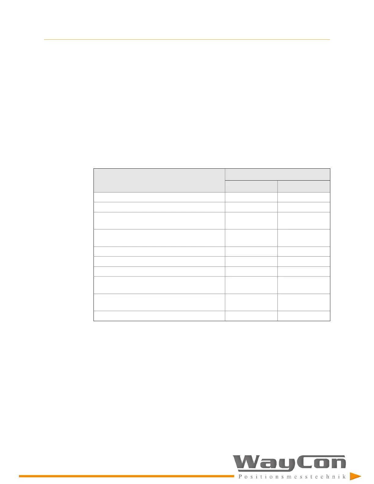
Table 5-1: Permissible wire cross-section
Wire description
Wire cross-section
Minimum
Maximum
Conductor cross section solid 0.34 mm² 2.5 mm²
Conductor cross section flexible 0.2 mm² 2.5 mm²
Conductor cross section flexible, with ferrule without
plastic sleeve
0.25 mm² 2.5 mm²
Conductor cross section flexible, with ferrule with
plastic sleeve
0.25 mm² 2.5 mm²
Conductor cross section AWG 24 12
2 conductors with same cross section, solid 0.2 mm² 1 mm²
2 conductors with same cross section, stranded 0.2 mm² 1.5 mm²
2 conductors with same cross section, stranded,
ferrules without plastic sleeve
0.25 mm 1 mm²
2 conductors with same cross section, stranded,
TWIN ferrules with plastic sleeve
0.5 mm² 1.5 mm²
AWG according to UL/CUL 30 12
The required wire stripping length is 10 mm.
Power supply and output signal connection
The EZ 1000 converter requires a -24 V DC power supply and is typically supplied by the
used measuring amplifiers such as an A6500-UM Universal Measurement Card. Usage of a
suitable external power supply is also possible.
If using an external power supply, ensure that it is a Class 2 power supply or a Limited
Energy source in accordance to CSA 61010-1-12.
Figure 5-4
exemplifies the connection of an EZ 1000. The shown grounding concept is one
possibility. Adapt the grounding concept to the on-site requirements.

 Loading...