19
Reference Manual
00809-0100-4108, Rev BA
Section 2: Configuration
March 2014
Configuration
Configuring LCD display with a field communicator
Configuring LCD display with AMS Device Manager
1. Right click on the device and select Configure.
2. Click Manual Setup, select the Display tab.
3. Select desired display options and click Send.
Configuring LCD display with a local operator interface
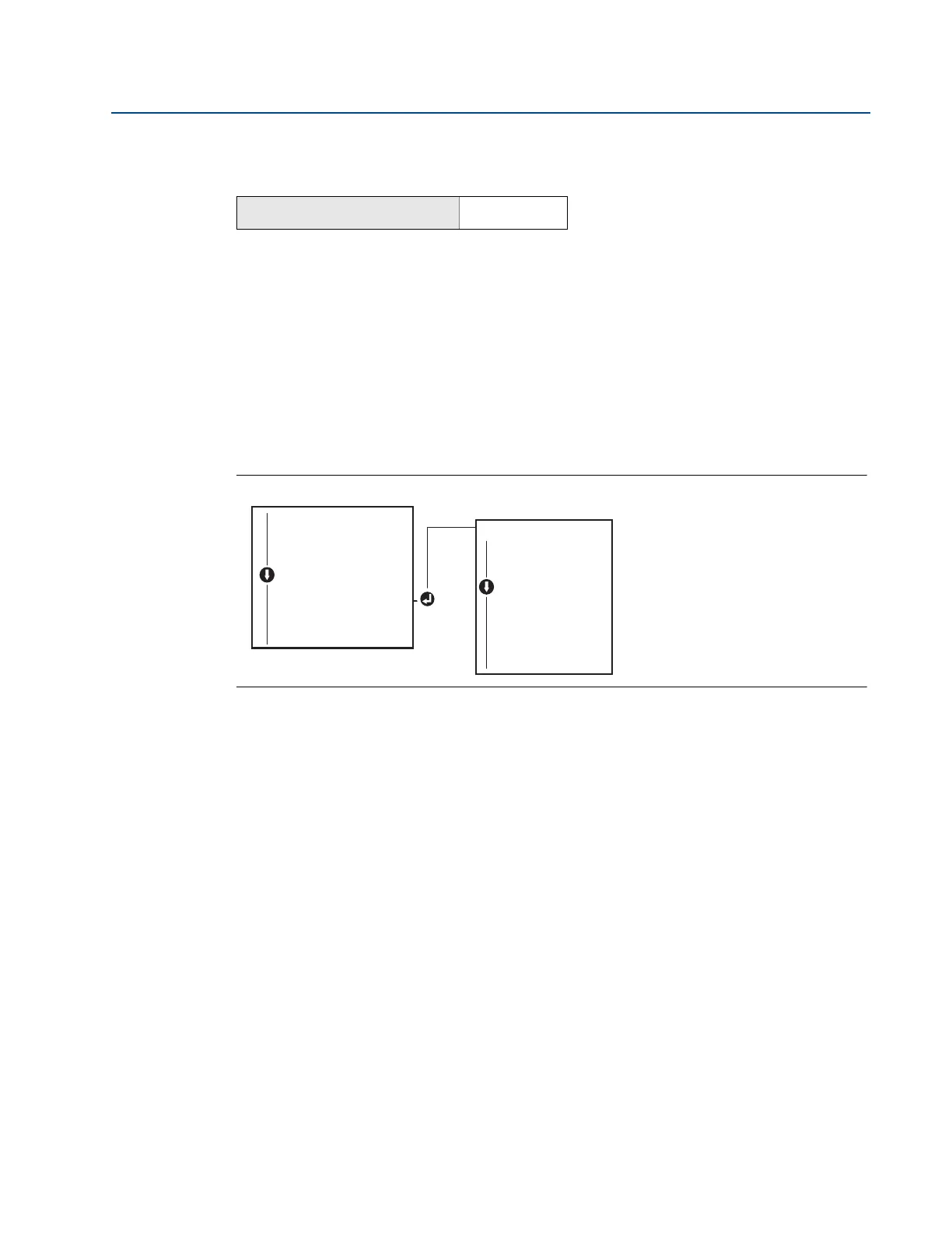
Refer to Figure 2-10 for LCD display configuration using a LOI.
Figure 2-10. Display with LOI
2.8 Detailed transmitter setup
2.8.1 Configuring alarm and saturation levels
In normal operation, the transmitter will drive the output in response to pressure from the lower
to upper saturation points. If the pressure goes outside the sensor limits, or if the output would
be beyond the saturation points, the output will be limited to the associated saturation point.
The Rosemount 2088 transmitter automatically and continuously performs self-diagnostic
routines. If the self-diagnostic routines detect a failure, the transmitter drives the output to
configured alarm and value based on the position of the alarm switch. See “Setting transmitter
alarm” on page 43.
From the HOME screen, enter the Fast Key sequence
Device Dashboard Fast Keys
2, 2, 4
DISPLAY
PRESS (on/off)
SCALED (on/off)
TEMP (on/off)
%RANGE (on/off)
ANALOG (on/off)
STRTUP (on/off)
BACK TO MENU
EXIT MENU
VIEW CONFIG
ZERO TRIM
UNITS
RERANGE
LOOP TEST
DISPLAY
DISPLAY
EXTENDED MENU
EXIT MENU
 Loading...