34
Reference Manual
00809-0100-4108, Rev BA
Section 3: Hardware Installation
March 2014
Hardware installation
3.4.2 Impulse piping
Mounting requirements
Impulse piping configurations depend on specific measurement conditions. Refer to Figure 3-2
on page 35 through Figure 3-4 on page 35 for examples of the following mounting configura-
tions:
Liquid measurement
Place taps to the side of the line to prevent sediment deposits on the transmitter’s
process isolator.
Mount the transmitter beside or below the taps so gases can vent into the process line.
Mount drain/vent valve upward to allow gases to vent.
Gas measurement
Place tap in the top or side of the line.
Mount the transmitter beside or above the tap so liquid will drain into the process line.
Steam measurement
Place tap to the side of the line.
Mount the transmitter below the taps to ensure that the impulse piping will stay filled
with condensate.
In steam service above 250 °F (121 °C), fill impulse line with water to prevent steam
from contacting the transmitter directly and to ensure accurate measurement start-up.
Note
For steam or other elevated temperature services, it is important that temperatures at the
process connection do not exceed the transmitter’s process temperature limits.
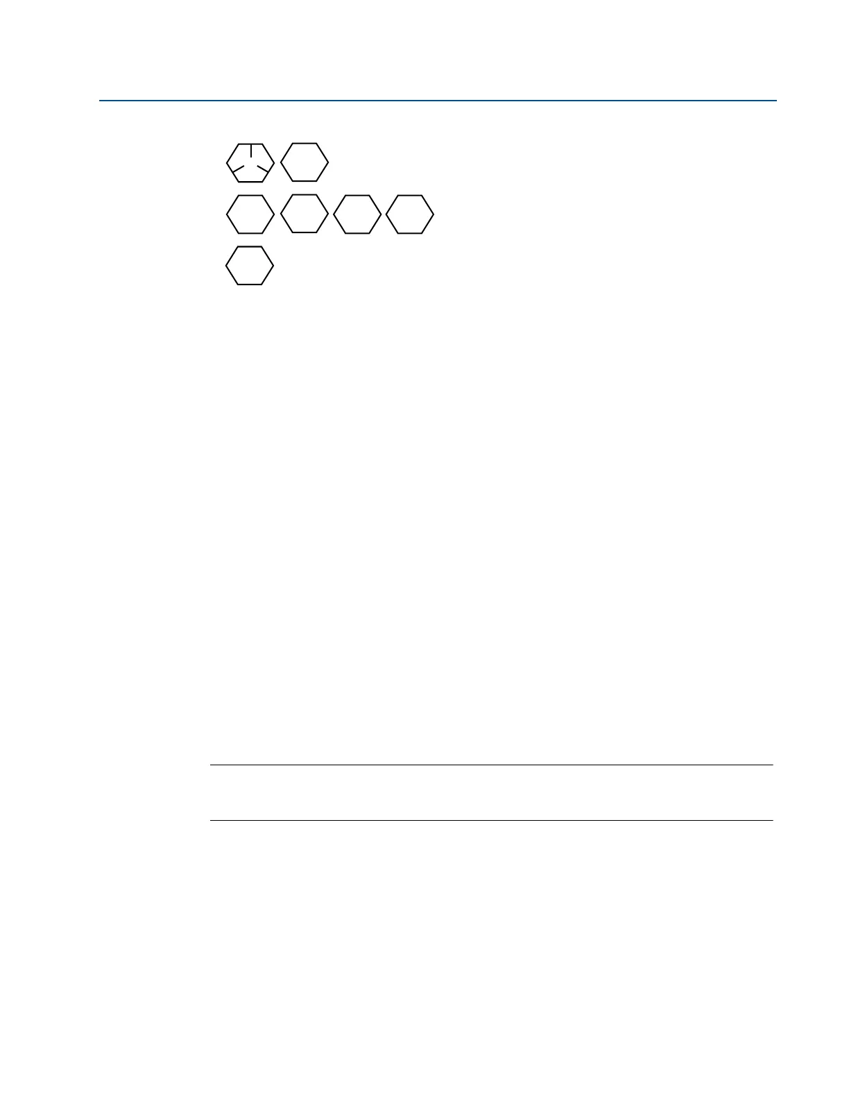
Carbon Steel (CS) Head Markings
B7M
316
B8M
F593_*
Stainless Steel (SST) Head Markings
KM
660
CL A
Alloy K-500 Head Marking
*The last digit in the F593_ head marking may be
any letter between A and M.
 Loading...