36
Reference Manual
00809-0100-4108, Rev BA
Section 3: Hardware Installation
March 2014
Hardware installation
Best practices
The piping between the process and the transmitter must accurately transfer the pressure to
obtain accurate measurements. There are five possible sources of error: pressure transfer, leaks,
friction loss (particularly if purging is used), trapped gas in a liquid line, liquid in a gas line, and
density variations between the legs.
The best location for the transmitter in relation to the process pipe is dependent on the process.
Use the following guidelines to determine transmitter location and placement of impulse
piping:
Keep impulse piping as short as possible.
For liquid service, slope the impulse piping at least 1 in./foot (8 cm/m) upward from the
transmitter toward the process connection.
For gas service, slope the impulse piping at least 1 in./foot (8 cm/m) downward from
the transmitter toward the process connection.
Avoid high points in liquid lines and low points in gas lines.
Use impulse piping large enough to avoid friction effects and blockage.
Vent all gas from liquid piping legs.
When purging, make the purge connection close to the process taps and purge
through equal lengths of the same size pipe. Avoid purging through the transmitter.
Keep corrosive or hot [above 250 °F (121 °C)] process material out of direct contact
with the sensor module and flanges.
Prevent sediment deposits in the impulse piping.
Avoid conditions that might allow process fluid to freeze within the process flange.
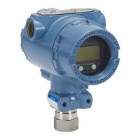
3.4.3 Process connections
3.4.4 Inline process connection
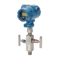
Inline gage transmitter orientation
The low side pressure port on the inline gage transmitter is located in the neck of the
transmitter, behind the housing. The vent path is 360 degrees around the transmitter between
the housing and sensor (See Figure 3-5).
Keep the vent path free of any obstruction, such as paint, dust, and lubrication by mounting the
transmitter so that the process can drain away.
Interfering or blocking the atmospheric reference port will cause the transmitter to output
erroneous pressure values.
 Loading...