43
Reference Manual
00809-0200-4728, Rev SA
Installation
July 2018
Installation
3.3.4 Mechanical
Location
When choosing an installation location and position, take into account the need for access to the
transmitter.
Special mounting
Special mounting hardware is available for mounting a Rosemount 644 Head Mount Transmitter to a DIN
rail or assembling a new Rosemount 644 Head Mount to an existing threaded sensor connection head
(former option code L1).
3.3.5 Electrical
Proper electrical installation is necessary to prevent errors due to sensor lead resistance and electrical
noise. For best results, shielded cable should be used in electrically noisy environments.
Make wiring connections through the cable entry in the side of the housing. Be sure to provide adequate
clearance for cover removal.
3.3.6 Environmental
The transmitter electronics module is permanently sealed within a plastic enclosure, resisting moisture
and corrosive damage. Verify that the operating atmosphere of the transmitter is consistent with the
appropriate hazardous locations certifications.
Temperature effects
The transmitter will operate within specifications for ambient temperatures between –40 and 185 °F
(–40 °C and 85 °C). Heat from the process is transferred from the thermowell to the transmitter housing.
If the expected process temperature is near or beyond specification limits, consider the use of additional
thermowell lagging, an extension nipple, or a remote mounting configuration to isolate the transmitter
from the process.
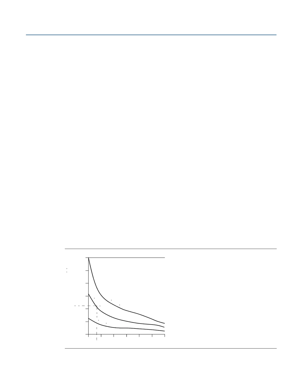
Figure 3-1 provides an example of the relationship between transmitter housing temperature rise and
extension length.
Figure 3-1. Head Mount Transmitter Connection Head Temperature Rise vs. Extension Length
60 (108)
50 (90)
40 (72)
30 (54)
20 (36)
10 (18)
0
34567 89
815 C (1500 F)
Oven Temperature
540 C (1000 F)
Oven Temperature
250 C (482 F)
Oven Temperature
Housing Temperature Rise Above Ambient C ( F)
Extension Length (in.)
3.6
22
 Loading...