59
Reference Manual
00809-0200-4728, Rev SA
Operation and Maintenance
July 2018
Operation and Maintenance
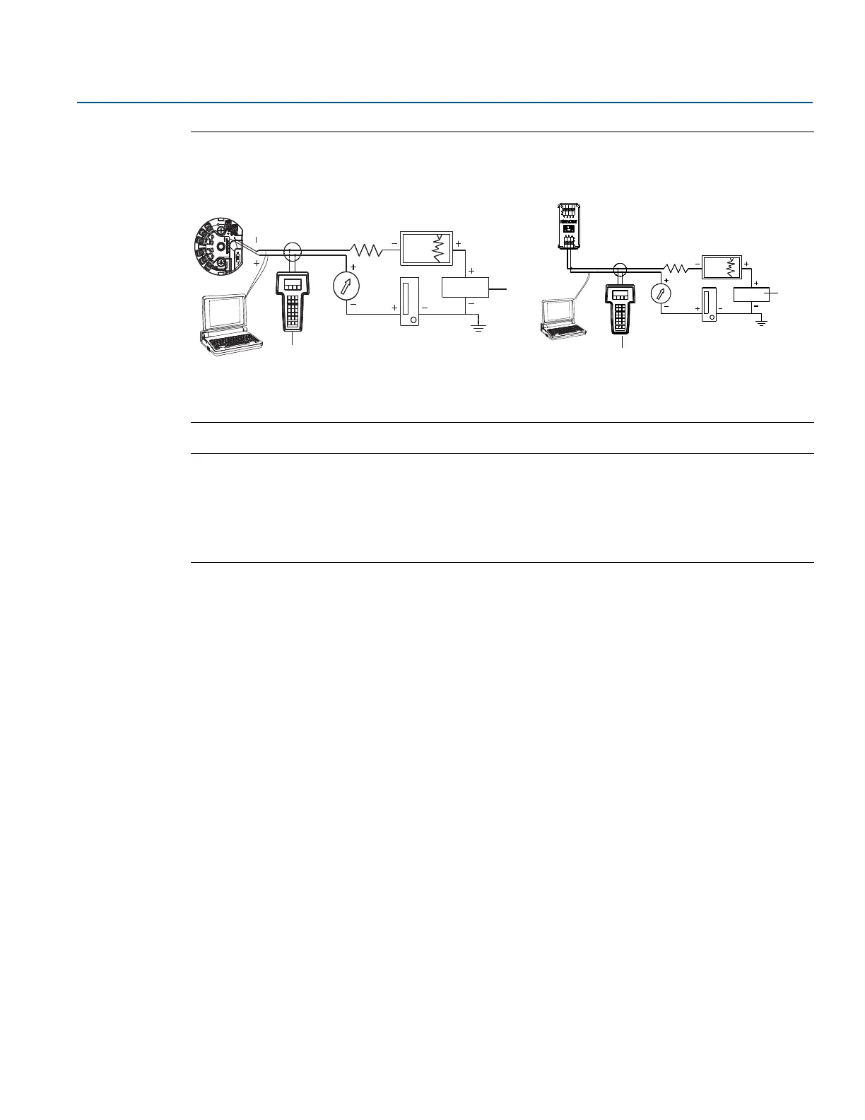
Figure 4-3. Powering the Transmitter for Bench Configuration
Note
Signal loop may be grounded at any point or left ungrounded.
A Field Communicator may be connected at any termination point in the signal loop. The signal loop
must have between 250 and 1100 ohms load for communications.
Max torque is 6 in-lb (
0
/7 N-m).
Load limitation
The power required across the transmitter power terminals is 12 to 42.4 Vdc (the power terminals are
rated to 42.4 Vdc). To prevent damaging the transmitter, do not allow terminal voltage to drop below
12.0 Vdc when changing the configuration parameters.
4.3.3 Ground the transmitter
Sensor shielding
The currents in the leads induced by electromagnetic interference can be reduced by shielding. Shielding
carries the current to ground and away from the leads and electronics. If the ends of the shields are
adequately grounded, only a small amount of current will actually enter the transmitter. If the ends of
the shield are left ungrounded, voltage is created between the shield and the transmitter housing and
also between the shield and earth at the element end. The transmitter may not be able to compensate
for this voltage, causing it to lose communication and/or go into alarm. Instead of the shield carrying the
currents away from the transmitter, the currents will now flow through the sensor leads into the
transmitter circuitry where it will interfere with the circuit operation.
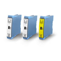
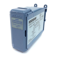
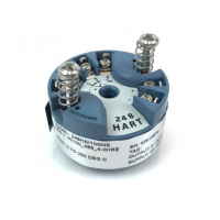
Rosemount 644 Head Mount and Field Mount Rosemount 644 Rail Mount
A. Power supply
B. Field Communicator
B
A
 Loading...