2-4 • Site Supervisor Controller User Guide 2.0 026-1800 Rev 3 02-AUG-2016
3. View the I/O network traffic status.
4. Navigate to the summary screen of a specific
device.
2.2.2.4 Zone Management
You can associate an RTU application with a zone.
Zone is a group of RTUs and/or AHU (air handling unit)
applications that shares the same heating, cooling,
dehumidification setpoints, and other control parameters.
The primary purpose of zone control is to maintain a
specific temperature and humidity level throughout a wide
area using multiple rooftop units.
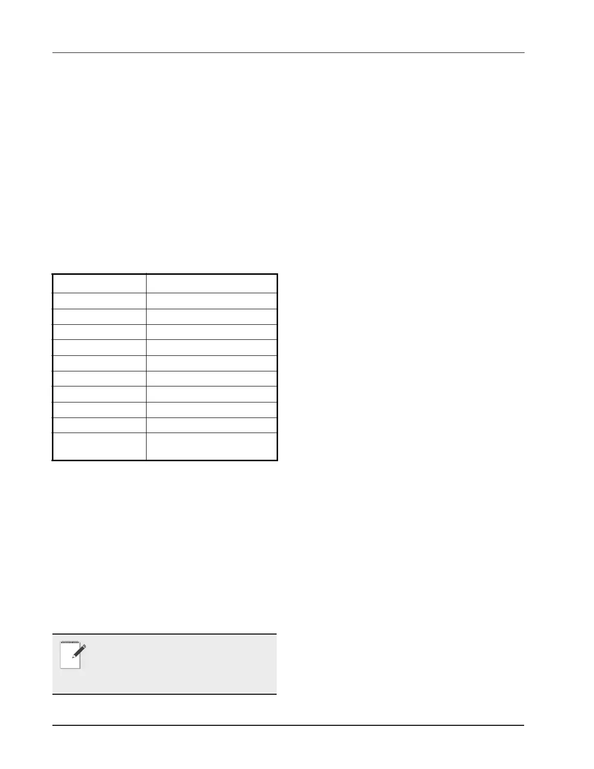
When an RTU application is associated with a zone,
some inputs of RTU application should use the output
values from zone. These are the property mapping list:
2.2.2.5 Scheduling
Daily (from Monday to Sunday) schedules of
Occupied/Unoccupied state can be set and send to the
RTU board.
2.2.2.6 Alarming
Alarms generated from RTU board will be received
and reported by Alarm management in Site
Supervisor.You can configure the attribution, type and
category of the alarms generated from RTU board.
Any reset or clear actions performed on the UI is
forwarded to the RTU board.
2.2.2.7 Real Time Clock Updates
Current system date or time is sent to the RTU board
periodically with a 10-second interval.
2.2.2.8 Hand-Held Terminal Support
1. You can connect to the RTU board with a hand-
held terminal (HHT) to read or write the
configuration of this RTU board.
2. When a HHT is connected to a RTU board, any
setpoint change made from UI will not be sent to
the RTU board. Some controllers will accept the
changes but some will not.
3. The Site Supervisor downloads all setpoints and
configuration parameters you changed from UI
upon receipt of a message from the RTU that the
hand-held terminal is disconnected. This will
overwrite any changes made using the HHT.
4. The Site Supervisor does not accept permanent
changes made via the hand-held terminal to the
Site Supervisor.
2.2.3 MultiFlex RCB Support
2.2.3.1 I/O Network and MultiFlex RCB
Setup on Serial Port
1. Navigate to serial port configuration screen,
select an unused port and configure it as an I/O
network port.
2. Configure the baud rate of the I/O network port,
then select MultiFlex RCB from the supported
board types for this port. Set the number of board
needed to setup, click Save to add the RCB
devices. RCB board status will appear Online.
3.Navigate to the “HVAC - RCB_0X” device
status screen through the site map, the status
screen displays the following sections:
• General
•Alarm Outs
• Inputs
• Outputs
• RCB Outputs
4. Click Details on the status screen, the system will
display the properties of the RCB board by the
properties group. You can now view and
configure the properties of the RCB board.
5. After configuring the properties, the new values
can be sent to RCB application on the Site
Supervisor and RCB board on the I/O network.
The RCB board can now work correctly on the
RTU Inputs Zone Outputs
ZONE OCC ZONE_OCC_STATE
ZONE TEMP ZONE_TEMP_OUT
ECONMIZE ZONE ECON OK
DEHUMDIFY ZONE DEHUM ACTIVE
OCC HEAT ZONE HEAT OCC OUT
UNOCC HEAT ZONE HEAT UOC OUT
OCC COOL ZONE COOL OCC OUT
UNOCC COOL ZONE COOL UOC OUT
OCC DEHUM ZONE FB HUMID STPT
SEASON ZONE_SUM_WIN_-
MODE_OUT
Table 2-3
- RTU and Zone Property Mapping List
NOTE: The RTU does not have the capability
of resetting individual alarms. All alarms on
the RTU will be reset or cleared by the RTU if
anyone reset or clear the alarms in the Site
Supervisor.
 Loading...