5-44 • Site Supervisor Controller User Guide 2.0 026-1800 Rev 3 02-AUG-2016
are not high enough to require a defrost.
The optical demand defrost sensor may be either an
analog or digital type sensor. When this sensor detects no
major build-up of frost, the Case Circuit application
ignores all scheduled calls for defrost and continues in
refrigeration mode. When the sensor detects frost, the
defrost inhibit is canceled, and the case circuit will enter
defrost at the next scheduled time.
A demand defrost inhibit only keeps scheduled
defrosts from occurring. Any manual calls for a defrost
cycle will occur as normal. CCB demand defrost is cur-
rently not supported in Site Supervisor. Demand sensors, if
present on the circuit, will be ignored.
Demand Fail-Safe Time
To protect against demand defrost sensors that may not
be working properly, a demand fail-safe time may be set
up. Demand fail-safe times limit the amount of time a
defrost inhibit may last. If a demand defrost sensor does
not detect frost for an amount of time equal to the Demand
Fail-Safe Time, the defrost inhibit is lifted and the circuit
will enter defrost at the next scheduled time.
5.27.4.5 Emergency Defrost
When necessary, a user can initiate an emergency
defrost cycle from a circuit. Emergency defrost cycles are
similar to normal defrost cycles, except an emergency
defrost cycle will ignore all calls for termination and
remain in defrost for the entire programmed defrost time.
• Emergency defrosts are initiated by the user.
• The WAIT State
When a Case Control Circuit application enters defrost
mode, it sends a message out to all case controllers in the
circuit to begin defrost at the same time. However, since
each case in a circuit will have its own termination sen-
sors, it is possible for some cases to terminate defrost
while defrosts in other cases continue.
When a case controller terminates defrost, it enters a
state of operation called “the WAIT state.” While in the
WAIT state, all refrigeration and defrost heat will remain
OFF. When the Case Control Circuit application detects
that all case controllers have entered the WAIT state, the
application will consider the defrost cycle completed, and
refrigeration will restart.
5.28 Irrigation Control
Irrigation control is an application used for the con-
trolling of sprinkler systems. This application controls
watering by duration of time or water usage parameters.
Days of the week and times for watering are set by the
user with a maximum of two Irrigation applications
allowed in the CX controller.
The master water valve is turned ON and OFF as water
is needed for a zone. When disabled, no application con-
trol of any outputs will be possible and the System Status
output will indicate Disabled.
Under normal control only one zone will be active at a
time.
How To Add a Irrigation Control Device on the Site
Supervisor:
1. From Home screen, navigate to Main Menu>
Summaries and Floor Plans> Site Summaries>
Other, click the screen drop-down arrow on the
upper right of the screen, click Add Controls.
2. Select the Control or Application Type -
Irrigation Control, enter the Quantity, Control
Name and Serial Type. Note that Serial Type
information can be enter later. Click Save to add
the application.
3. A Confirmation box will appear saying that the
application is successfully added to the system,
click Close or Edit these controls.
4. The system will display the new application(s) on
the Site Summary screen.
5. Click the Irrigation Control application panel box
to view the application.
6. The system will display the Irrigation Control
application parameters.
7. The user can view and configure the properties of
the application by setting the Edit Mode to ON
on the screen drop-down arrow on the upper right
of the screen.
5.29 TD Control
5.29.1 Overview
The TD Control application controls fans sequentially
based on the temperature differential (TD) of the con-
denser. When an increase is called for, the next fan will
turn on when the time since the last fan state change is
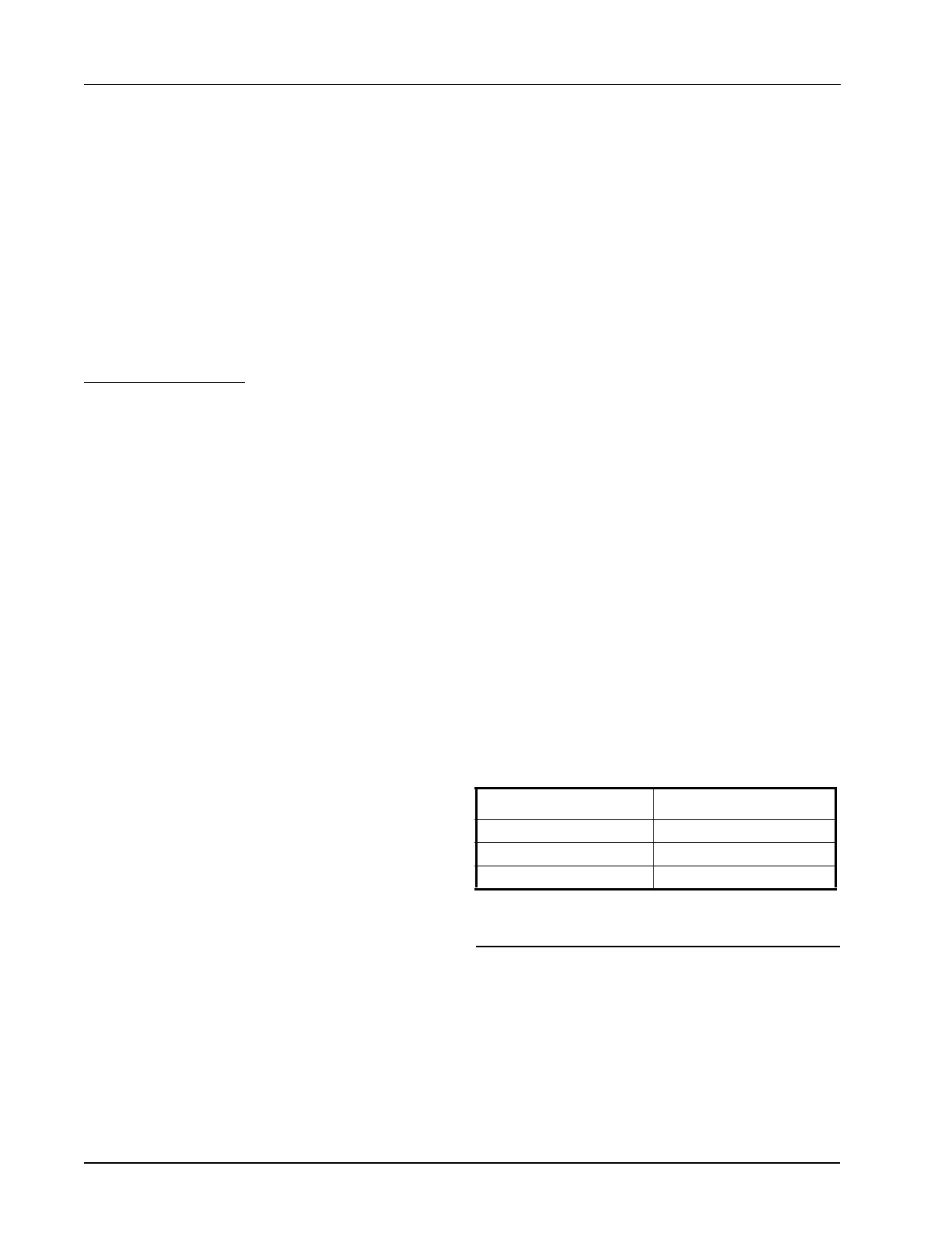
Application Advisories Heating
Flow obstructed Non-critical
Leak detected Non-critical
Inhibit Sensor Failed Non-critical
Table 5-15- Irrigation Control Advisories
 Loading...