5-26 • Site Supervisor Controller User Guide 2.0 026-1800 Rev 3 02-AUG-2016
5.12 XC645CX 2.5
The XC645CX is designed to manage both
compressors and fans in a condensing system such as a
pack. The compressors can be digital scroll, simple,
multistage. Control is by means of a neutral zone or
proportional band and is based on the pressure or
temperature sensed in the LP suction (compressors) and
HP (condenser) circuits. A special algorithm balances the
run hours of the compressors to distribute the work load
uniformly. The controllers can convert both LP and HP
pressures and displays them as temperatures. The front
panel offers complete information on the system's status
by displaying the suction and condenser pressure
(temperatures), the status of the loads, possible alarms or
maintenance conditions. Each load has its own alarm input
that is able to stop it when activated. Additionally, there
are two inputs for low and high pressure switches: when
these are activated, the system is stopped. The controller
can be easily programmed at power-on by using the Hot
Key. The controller can be connected to the XWEB
controlling and monitoring system, through the TTL
output, using the standard MODBUS RTU protocol.
How To Add an XC645 2.5 Device on the Site
Supervisor:
1. From Home screen, navigate to Main Menu>
Summaries and Floor Plans> Site Summaries>
Refrigeration, click the screen drop-down arrow
on the upper right of the screen, click Add
Controls.
2. Select the Control or Application Type -
XC645CX 2.5, enter the Quantity, Control Name
and Serial Type. Note that Serial Type
information can be enter later. Click Save to add
the application.
3. A Confirmation box will appear saying that the
application is successfully added to the system,
click Close or Edit these controls.
4. The system will display the new application(s) on
the Site Summary screen.
5. Click the XC645CX 2.5 application panel box to
view the application.
6. The system will display the XC645CX 2.5
application parameters.
7. The user can view and configure the properties of
the application by setting the Edit Mode to ON
on the screen drop-down arrow on the upper right
of the screen.
5.12.1 Application Advisories
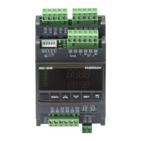
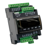
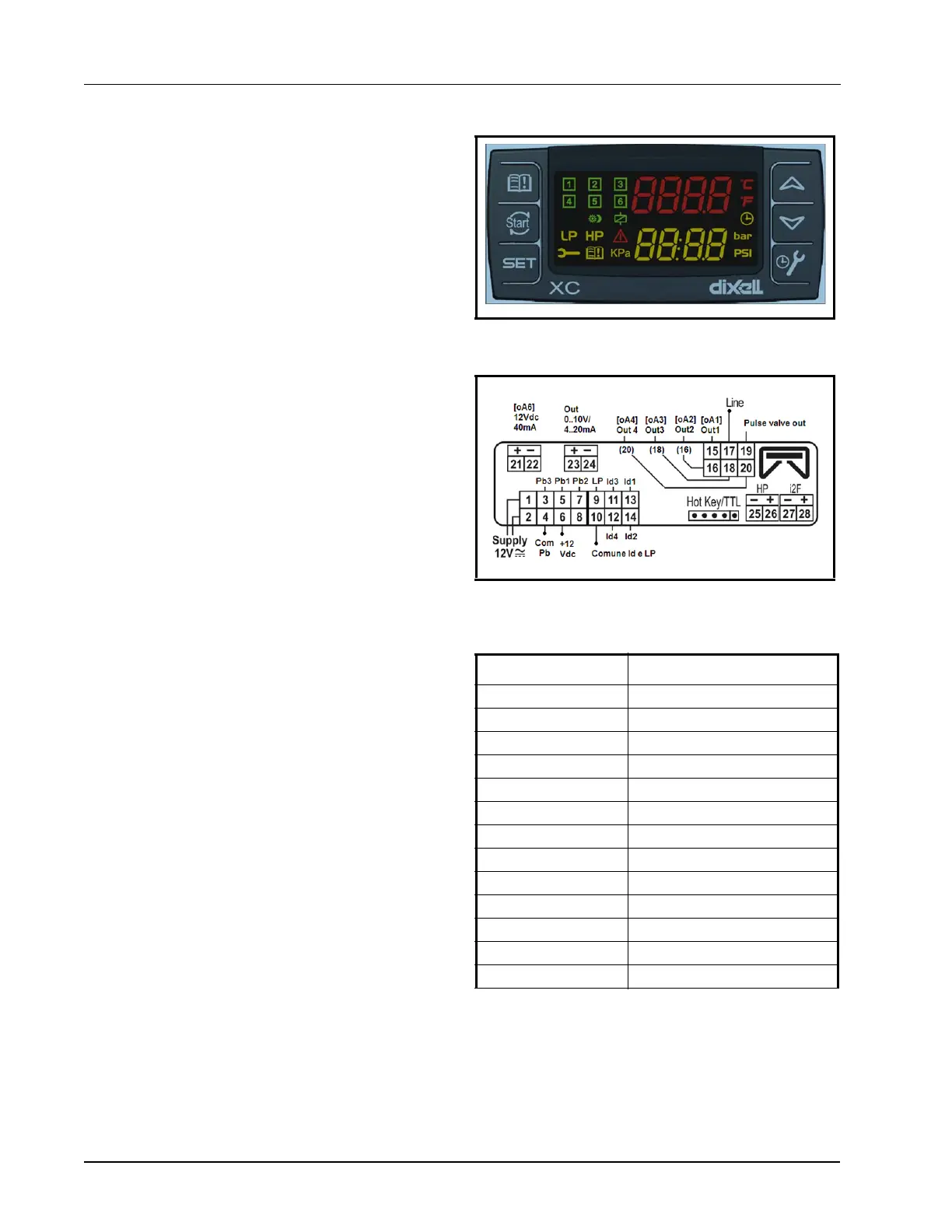
Figure 5-7 - XC645CX 2.5 Device
Figure 5-8 - XC645CX 2.5 Wiring
Alarm Description
ERROR PB1 Error Pb1
ERROR PB2 Error Pb2
ERROR PB3 Error Pb3
LIQUID LEVEL Liquid Level Alarm
LOW SUCT ALARM Low Suction Alarm
HIGH SUCT ALARM High Suction Alarm
LOW COND ALARM Low Condens. Alarm
HIGH COND ALARM High Condens. Alarm
LOAD 1 ALARM Load 1 Alarm
LOAD 2 ALARM Load 2 Alarm
LOAD 3 ALARM Load 3 Alarm
LOAD 4 ALARM Load 4 Alarm
LOAD 5 ALARM Load 5 Alarm
Table 5-7 - XC645CX 2.5 Application Advisories
 Loading...