2 – 6
VSS/VSR/VSM/VSH/VSSH Compressor • Installation, Operation and Service Manual • Emerson • 35391S
Section 2 • Theory of Operation
Single Screw Package Requirements
Process Gas Circuit
1. Suction Gas Stop/Check Valve - The Single Screw
compressor requires a manually operated stop valve on
the suction line to the compressor to allow for isolating
the compressor package from process gas. Also, a check
valve is required in the suction line to limit reverse rota-
tion of the compressor on shutdown.
2. Suction Line Strainer - Vilter
TM
strongly recommends
the use of an in-line suction gas strainer to protect the
Single Screw compressor from foreign material which
may enter the compressor with the suction gas. This
strainer is generally of stainless steel mesh construction.
3. Process Gas/Oil Separator - A separator vessel ca-
pable of removing the oil from the discharge gas stream
with an efciency down to at least 5 PPM oil carryover
is required. Vilter’s own available horizontal or vertical
separator is an ASME-coded vessel which uses ve stages
of separation to achieve an oil loss of as little as 3 to 4
PPM.
4. Discharge Gas Relief Valve - To protect the compres-
sor package from damage due to over pressurization, a
relief valve must be installed inside of any discharge line
hand block valves. The relief valve must be set to open at
a pressure lower than the Maximum Allowable Working
Pressure (MAWP) of the separator.
5. Oil Prelube Pump - Usually a direct driven gear type
pump, the oil pump is required to prelube the compres-
sor prior to starting and to maintain oil pressure during
any periods of low compression ratio operation.
6. Oil Cooler/ Temperature Control Valve - An oil cooler,
either air or water cooled, must be used to remove the
heat of compression from the oil stream. A temperature
control valve is used to maintain constant oil injection
temperature to the compressor.
7. Oil Filtration - Large capacity micronic oil lters are
required to lter the oil before injection into the Single
Screw compressor. Filtration down to 25 microns nomi-
nal or less is generally acceptable. Dual lters are recom-
mended to allow replacement of one cartridge while the
compressor continues running with the other cartridge
in service. If needed, separate oil ltration can be avail-
able for bearings and shaft seal.
8. Oil Heater - An oil heater is generally required and
must be sized to maintain oil temperature of at least
90°F when the compressor is not running. For outdoor
installations, low ambient temperatures and winds must
be considered when sizing the oil heater. Also, insulating
the separator and oil piping may be required in low tem-
perature ambient conditions.
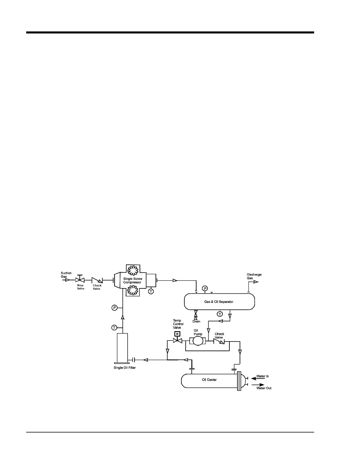
Figure 2-2. Basic Single Screw Compressor System

 Loading...


