5 – 29
Section 5 • Maintenance/Service
VSS/VSR/VSM/VSH/VSSH Compressor • Installation, Operation and Service Manual • Emerson • 35391S
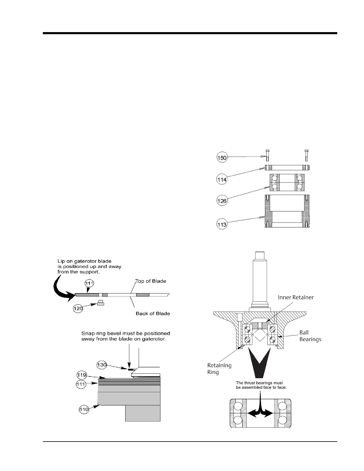
Gaterotor Thrust Bearing Installation
For installation of thrust bearings on VSS units
22. Install thrust bearings (126) in the housing so the
bearings are face to face. The larger sides of the in-
ner races are placed together. A light application
of clean compressor lubricating oil should be used
to ease the installation of the bearings into the
housing.
23. Center the bearing retainer ring on housing, use
Loctite® 242-thread locker and evenly tighten
the bolts to the recommended torque value, see
Figure 5-34.
Figure 5-32. Gaterotor Blade Installation
Figure 5-33. Gaterotor Thrust Bearing
Gaterotor Blade Installation
13. Install damper pin bushing (120) in gaterotor blade
(111) from the back side of the blade. Be sure bush-
ing is fully seated using red Loctite (271).
14. Place blade assembly on gaterotor support.
Locating damper over pin.
15. Install washer (119) and snap ring (130) on gatero-
tor assembly. The bevel on the snap ring must face
away from the gaterotor blade. After the gaterotor
blade and support are assembled, there should be
a small amount of rotational movement between
the gaterotor and support.
Gaterotor Thrust Bearing Removal
For removal of thrust bearings on VSM units:
16. Remove bolts (150) from the clamping ring (114),
see Figure 5-33.
17. Remove thrust bearing clamping ring.
18. Remove thrust bearings (126) from housing (113).
For removal of thrust bearings on VSS units:
19. Remove retaining ring from gaterotor support.
20. Remove bearings from support.
21. Remove bearing retainer from inner race.
Figure 5-34. Thrust Bearing Installation

 Loading...


