3 – 1
Section 3 • Installation
VSS/VSR/VSM/VSH/VSSH Compressor • Installation, Operation and Service Manual • Emerson • 35391S
NOTICE
Vilter compressors are to be installed and connected
to the customer-provided piping. Vilter expects this
piping to be designed and built following ASME B31.3
Process Piping Guide, plus any other local applicable
codes, and that the installation will be performed by
qualifi ed personnel only.
Delivery Inspection
Every equipment supplied by Vilter is thoroughly in-
spected at the factory. However, damage can occur in
shipment. For this reason, the compressor should be
thoroughly inspected upon arrival, prior to off-loading.
Any damage noted should be photographed and report-
ed immediately to the transportation company. This
way, an authorized agent can examine the compres-
sor, determine the extent of damage and take neces-
sary steps to rectify the claim with no serious or costly
delays. At the same time, the local Vilter representa-
tive or the home ofce should be notied of any claims
made within ten (10) days after its discovery. Refer to
Compressor Inspections Prior to Installation for addi-
tional recommendations.
Rigging and Lifting of the Compressor
WARNING
When rigging and lifting a compressor unit, use proper
lifting device capable of lifting and maneuvering the
weight and size of the compressor unit. Use only
qualifi ed personnel and additional personnel and
lifting equipment (i.e. spreader bar) as required.
Failure to comply may result in death, serious injury
and/or damage to equipment.
Only qualied personnel shall operate rigging and lifting
equipment. Ensure that the lifting device is capable of
lifting the weight of the compressor, refer to the sup-
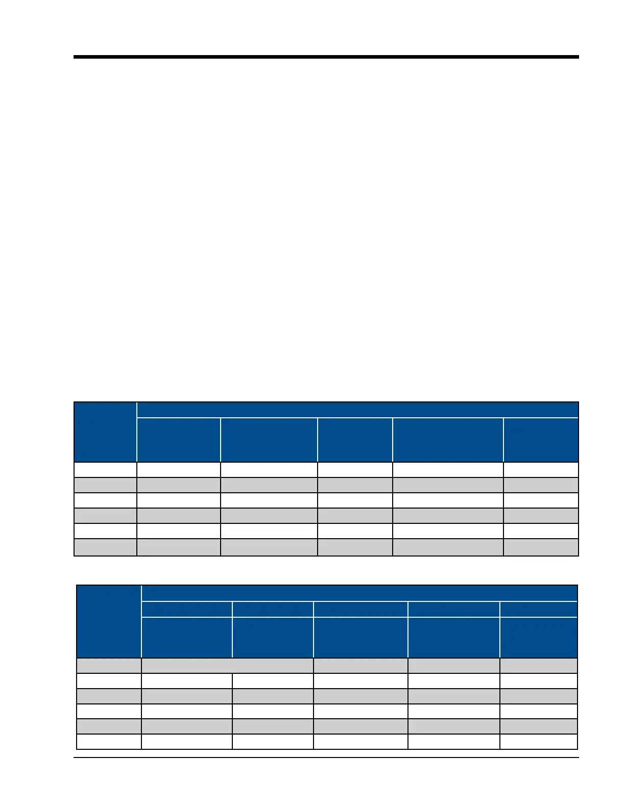
plied Vilter General Assembly (GA) drawing, and to Table
3-1 for weights of bare shaft compressors.
Models
Component Weights
Gaterotor
Bearing Housing
Gaterotor Bearing
Housing Cover
Discharge
Manifold
Main Compressor
Assembly ONLY
Gaterotor
Cover
97-127 3.3 lbs (1.6 kg) 8 lbs (4 kg) N/A 249 lbs (113 kg) 10 lbs (5 kg)
291-601 19 lbs (9 kg) 11 lbs (5 kg) 125 lbs (57 kg) 1105 lbs (502 kg) 46 lbs (21 kg)
751-901 28 lbs (13 kg) 11 lbs (5 kg) 177 lbs (80 kg) 1450 lbs (658 kg) 33 lbs (15 kg)
1051-1301 37 lbs (17 kg) 13 lbs (6 kg) 274 lbs (125 kg) 2006 lbs (910 kg) 42 lbs (19 kg)
1501-2101 54 lbs (24 kg) 19 lbs (9 kg) 349 lbs (158 kg) 3151 lbs (1429 kg) 70 lbs (32 kg)
2401-3001 58 lbs (27 kg) 32 lbs (15 kg) 788 lbs (358 kg) 4152 lbs (1883 kg) 150 lbs (68 kg)
Table 3-1. Bareshaft Compressor Component Weights
Models
Component Lifting Hole Sizes
A B C D E
Discharge
Manifold (Side)
Discharge
Manifold (Top)
Main Compressor
Assembly ONLY
(Discharge)
Main Compressor
Assembly ONLY
(Suction)
Gaterotor
Cover
97-127 A & B Lifting Points: 1/2 - 13 UNC -2B - - -
291-601 5/8-11 UNC -2B 5/8-11 UNC -2B 5/8-11 UNC -2B 5/8-11 UNC -2B 3/8-16 UNC-2B
751-901 5/8-11 UNC -2B 5/8-11 UNC -2B 5/8-11 UNC -2B 5/8-11 UNC -2B -
1051-1301 5/8-11 UNC-2B 5/8-11 UNC -2B 3/4-10 UNC -2B 5/8-11 UNC -2B 3/8-16 UNC -2B
1501-2101 5/8-11 UNC -2B 5/8-11 UNC -2B 5/8-11 UNC -2B 5/8-11 UNC -2B 3/8-16 UNC -2B
2401-3001 5/8-11 UNC -2B 5/8-11 UNC -2B 5/8-11 UNC -2B 3/4-10 UNC -2B 5/8-11 UNC -2B
Table 3-2. Bareshaft Compressor Component Lifting Hole Sizes
Bareshaft Compressor Lifting Points and Weights

 Loading...


