5 – 32
Section 5 • Maintenance/Service
VSS/VSR/VSM/VSH/VSSH Compressor • Installation, Operation and Service Manual • Emerson • 35391S
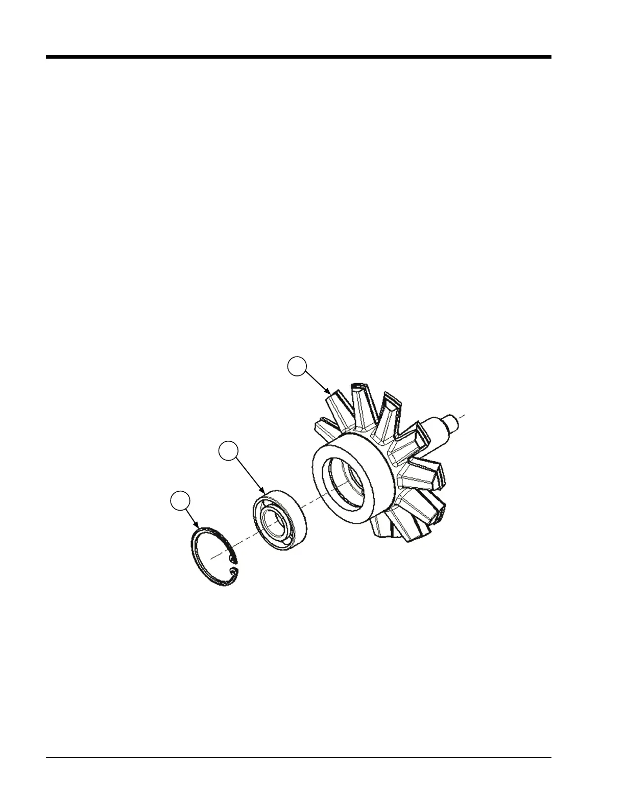
Figure 5-38. Gaterotor Thrust Bearing (VSM 97-127)
Gaterotor Roller Bearing Removal
11. Remove the snap ring, which retains the roller bear-
ing in the bearing housing.
12. Remove the roller bearing from the bearing
housing.
13. Use a bearing puller to remove the roller bearing
race from the gaterotor support.
Gaterotor Roller Bearing Installation
14. Match up the part numbers on the inner race to
the part numbers outer race. Press the bearing race
(numbers visible) onto the gaterotor support.
15. Install the outer bearing into the bearing housing
so the numbers match the numbers on the inner
race. Install the snap ring retainer in the housing.
The bevel on the snap ring must face away from the
roller bearing.
101
104
103
Install Retainer Ring
With Beveled Facing
Away From Gaterotor
Gaterotor Thrust Bearing Removal
(See Figure 5-38)
7. Remove retaining ring from gaterotor support.
8. Remove bearings from support.
9. Remove bearing retainer from inner race.
Gaterotor Thrust Bearing Installation
10. Install thrust bearings in the housing so the bearing
is face out (face is visible when installed). A light ap-
plication of clean compressor lubricating oil should
be used to ease the installation of the bearings into
the housing, see Figure 5-38.

 Loading...


