5 – 15
Section 5 • Maintenance/Service
VSS/VSR/VSM/VSH/VSSH Compressor • Installation, Operation and Service Manual • Emerson • 35391S
Gaterotor Bearing Inspection
1. Position a one gallon (at least) plastic oil collec-
tion bin beneath the side cover. Carefully pry
open the side cover to allow the oil to drain before
nally re moving the side cover.
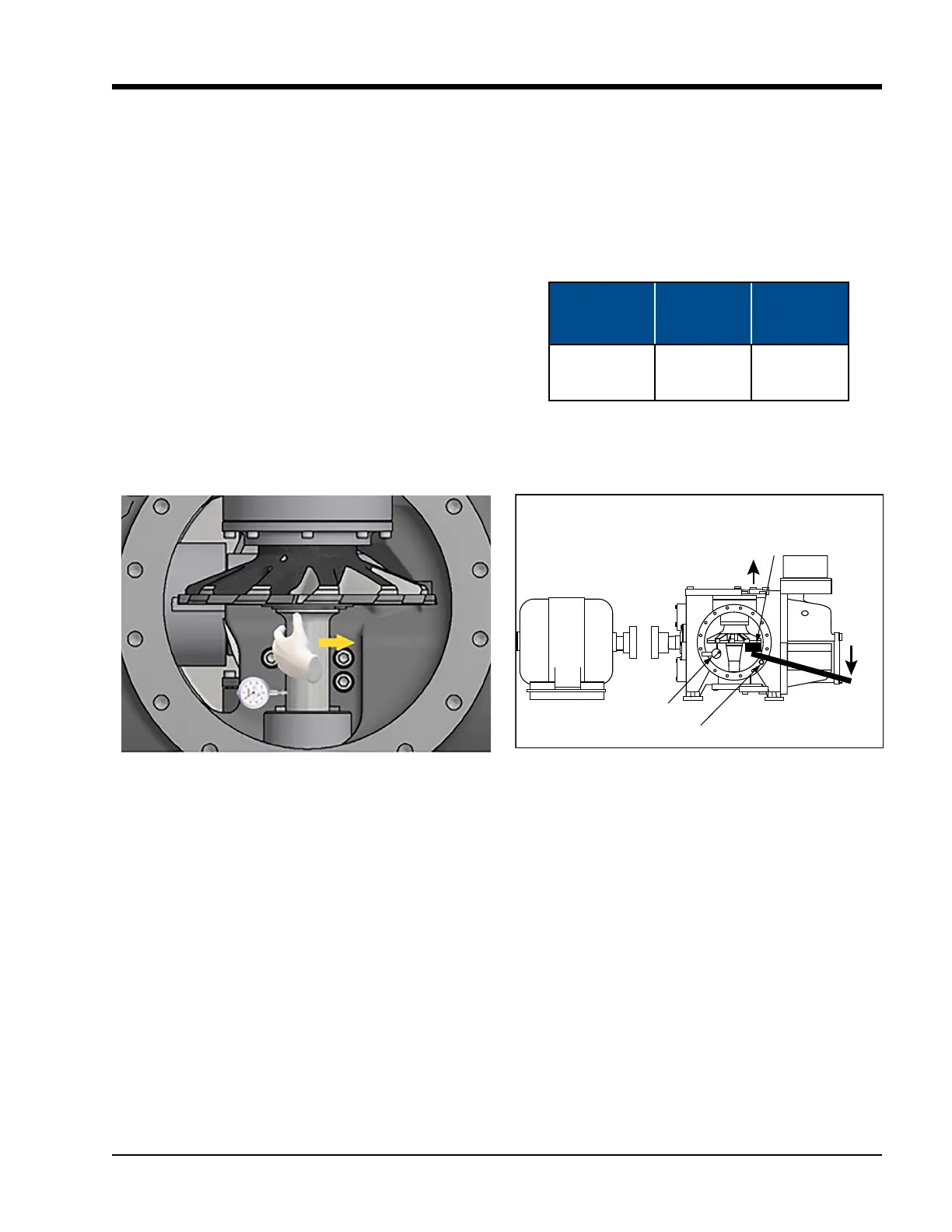
2. To measure the gaterotor radial bearing clear-
ance, position a dial indicator to the gaterotor
shaft as shown in Figure 5-10 (a) and zero the
indicator. Put a hand as shown and rmly move
the shaft in the direction shown in Figure 5-10
(a). Record the measurement. See table 5-4 for
the maximum radial clearance value.
3. To measure the gaterotor axial bearing clear-
ance, position a dial indicator on the gaterotor,
as shown in Figure 5-10 (b).
Figure 5-10. Gaterotor Bearing Clearance
Force to be determined
by length of lev
er
arm.
Use bolt for fulcrum.
Rigidly at tach
dial indicator.
Side View
Wooden block to prevent
damage to gaterotor blade.
Showing gaterotor bearing clearance
being measured.
Direction of gaterotor movement.
Axial force at gaterotor to not
exceed 100 lbs.
Figure 5-10 (b): Axial
Figure 5-10 (a): Radial
Compresso r
Models
Max. Axial
Clearance
in (mm)
Max. Radial
Clearance
in (mm)
All Sizes
0.002”
(0.051 mm)
0.004”
(0.102 mm)
Table 5-4. Maximum Gaterotor
Bearing Clearance
4. To check axial bearing clearance use a lever arm
pivoting on a bolt with a small block of wood
against the gaterotor to protect it, as shown in
Figure 5-10 (b). Record the measurement. See
Table 5-4 for the maximum axial clearance value.

 Loading...


