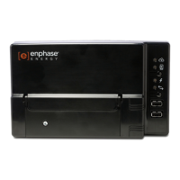
1. Choose a Location for the Envoy-S
a. Install the Envoy-S near the switchboard. This ensures that the Envoy-S receives the strongest
possible communications signal from each device. When installing the Envoy-S Metered,
consider the length of the CT leads when choosing the location. If you need to extend the CT
leads, see “Extend CT Leads, If Needed” on page 16.
b. Install the Envoy-S in a protected dry space (such as a garage, attic, basement, or other cool, dry
location). If the Envoy-S is hard-wired outdoors, you must install it inside an IP54-rated, (or
better) enclosure with conduit attachment. Use an appropriately rated enclosure if hard-wiring
indoors.
NOTE: Metallic enclosures may impair Wi-Fi signal strength.
c. Mount the Envoy horizontally using the included DIN rail.
WARNING: Risk of equipment damage. When installing the Envoy-S in an enclosure,
choose area for installation where ambient temperature does not exceed 46º C.
d. To wall-mount, use two appropriately sized screws and a screwdriver. Mount the DIN rail first,
and then clip the Envoy-S to the DIN rail.
2. Provide a Power Connection
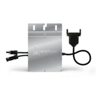
The Envoy-S Metered Multiphase (ENV-S-WM-230) uses terminal blocks for power and metering
connections. It does not include an AC power cord, and you must hard-wire it. When you hard-wire the
Envoy-S outdoors, you must install it in an IP54-rated, or better enclosure with conduit attachment. Use
an appropriately rated enclosure if hard-wiring indoors.
DANGER! Risk of electric shock. Be aware that installation of this equipment includes risk
of electric shock. If you wire the Envoy-S at the sub-board, always de-energise the sub-board
before beginning wiring.
a. Depending on the number of phases you will wire, use a one-, two-, or three-pole (20 A maximum)
circuit breaker for the supply wiring.
b. Make sure supply wiring is 2.5 mm
2
copper rated at 75º C or better.
c. Locate the screw on the terminal block door, and loosen it with a screwdriver to unlock the door
and flip it open.
d. Depending on the number of phases to wire, connect Line 1 to L1, Line 2 to L2, Line 3 to L3, and
Neutral to N, as required.
e. Tighten all connections to 0.56 Nm.
f. Refer to the following wire colour table, if needed:
 Loading...