C8 Maintenance 5. Joint #1
C Series Maintenance Manual Rev.2 293
Removal: Joint #1 Electromagnetic brake (M/C Cable Backward)
1. Remove the Joint #1 electromagnetic brake from the Joint #1 motor unit.
For details, refer to C8 Maintenance: 5.1.1 Joint #1-Replacing the Motor (M/C Cable Backward),
Removal steps (1) to (6).
Do not disconnect the connector BT1. If the connector is disconnected, perform calibration.
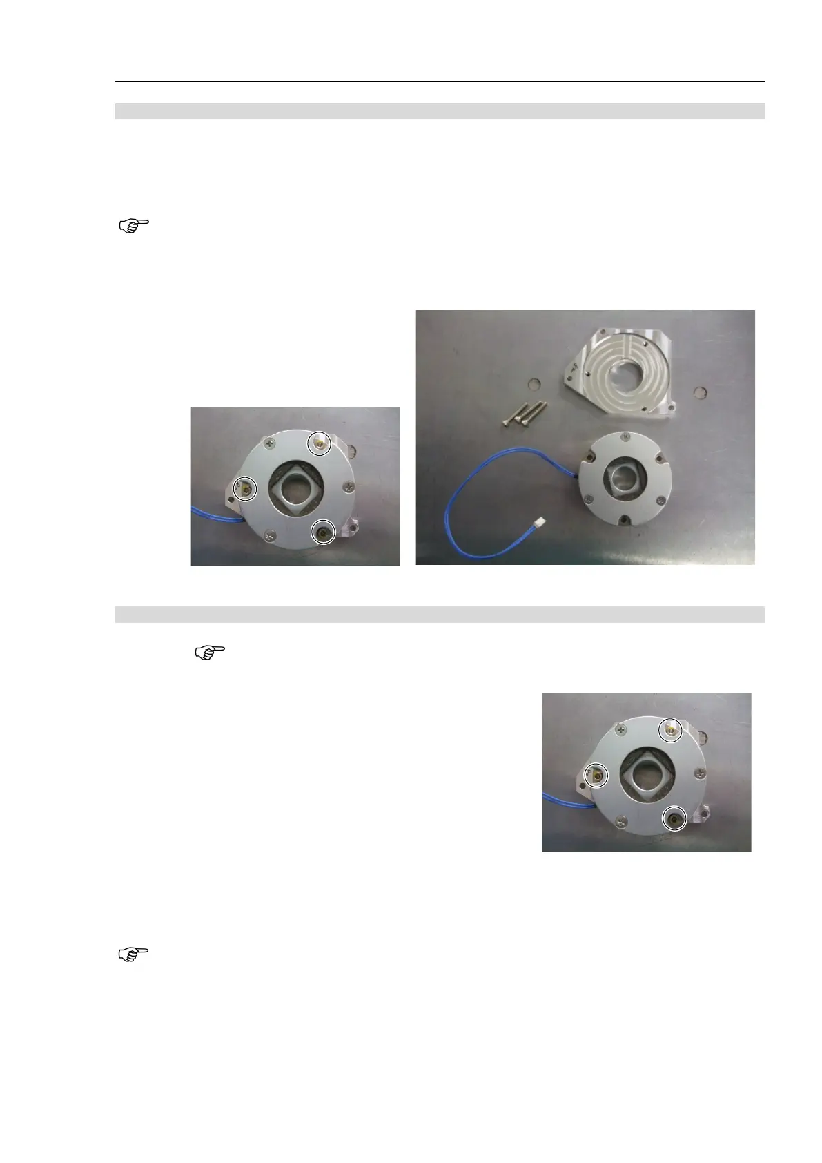
2. Remove the Joint #1 brake from the brake plate.
Hexagon socket head cap bolts: 3-M4×25
Installation: Joint #1 Electromagnetic brake (M/C Cable Backward)
When tightening hexagon socket head cap bolts, refer to the 2.4 Tightening Hexagon Socket
Head Cap Bolts.
1. Install the Joint #1 brake to the brake plate.
Hexagon socket head cap bolts: 3-M4×25
Tightening torque: 4.0 ± 0.2 N·m
Be careful of the assembly direction of the Joint #1
electromagnetic brake. (See the photo)
2. Mount the Joint #1 brake plate to the Joint #1 motor unit.
For details, refer to C8 Maintenance: 5.1.1 Joint #1-Replacing the Motor (M/C Cable Backward),
Installation steps (4) to (8).
If you disconnected the connector BT1 in the removal steps, perform calibration.
 Loading...


