C8 Maintenance 7. Joint #3
C Series Maintenance Manual Rev.2 343
7.4 Joint #3 - Replacing the Electromagnetic Brake
Maintenance
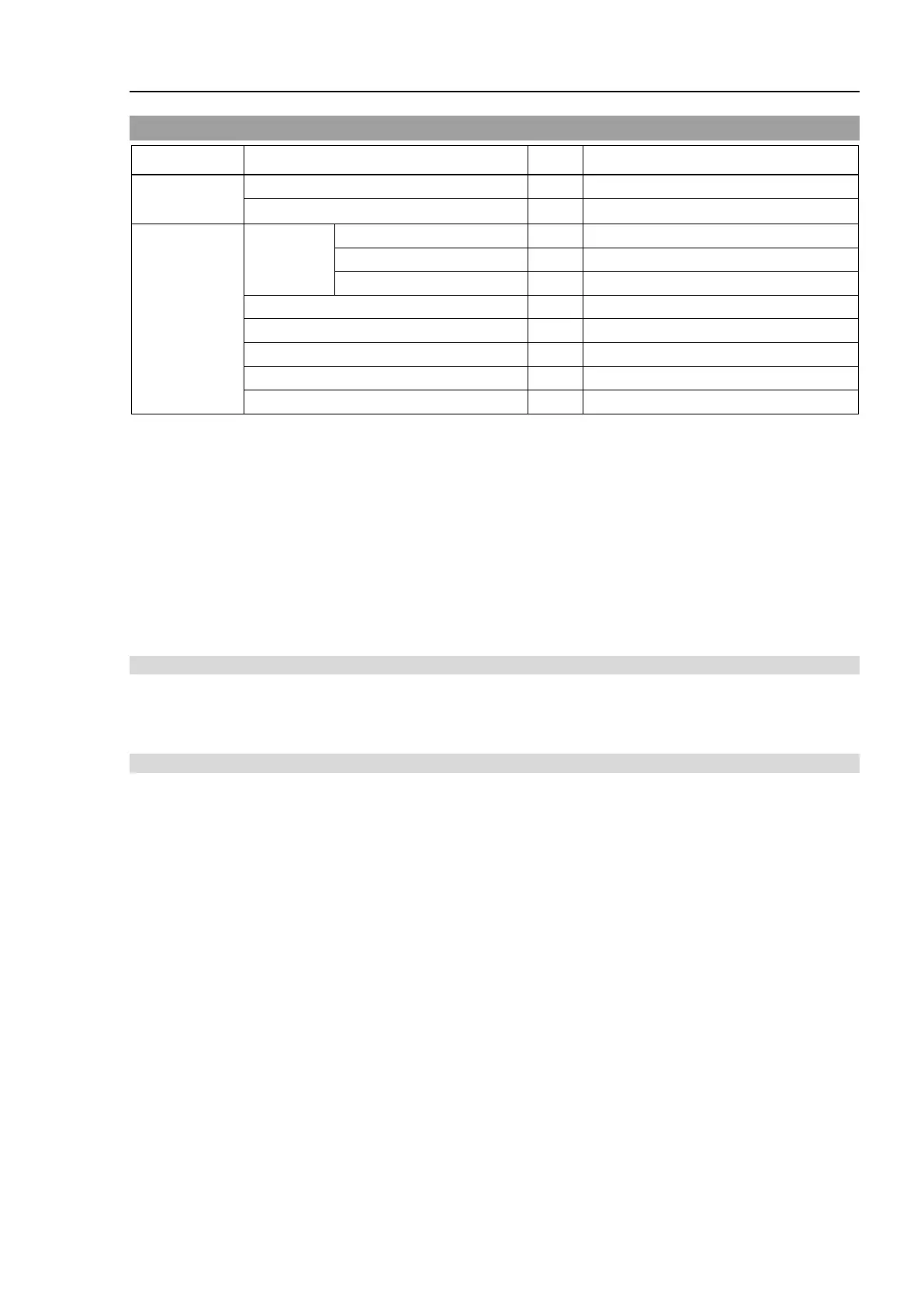
Electromagnetic brake (Joint #3)
Tools
Hexagonal
wrench
width across flats: 2.5 mm
For M5 hexagon socket set screw
For M4 hexagon socket head cap bolt
For M5 hexagon socket head cap bolt
Cross-point screwdriver (#2)
For cross recessed head screws
For tightening torque control
For adjusting the pulley position
* The belt tensile jig is an assembly jig. Use the jig when adjusting belt tension.
The brake is mounted on each joint to prevent the arm from lowering due to its own weight while the
Controller power is OFF or the motor is OFF status. The brake does not work during replacement. Be
careful when performing maintenance work.
When removing the Joint #3 motor, tilt the Arm #2 and press it against the Arm #2.
Reference: C8 Maintenance: 7.1 Joint #3 - Replacing the Motor, Removal step (2)
When pressing the arm, put a piece of cloth or a similar material between the arms to avoid contacting each
other. This protects the arm surfaces from scratching and paint peeling off.
Removal: Joint #3 Electromagnetic brake
1. Remove the Joint #3 electromagnetic brake.
For details, refer to C8 Maintenance: 7.1 Joint #3 – Replacing the Motor, Removal steps (1) through (10).
Installation: Joint #3 Electromagnetic brake
1. Mount the Joint #3 electromagnetic brake to the Joint #3 motor unit.
For details, refer to C8 Maintenance: 7.1 Joint #3 – Replacing the Motor, Installation steps (2) through
(10).
 Loading...


