C4 Maintenance 5. Joint #1
72 C Series Maintenance Manual Rev.2
5.4 Joint #1 - Replacing the Electromagnetic Brake
Maintenance
Parts
Joint #1 electromagnetic brake
1
For the part code, refer to the
17. C4
Maintenance Part List.
1
Tools
Hexagonal
width across flats: 2.5 mm
For M5 hexagon socket head set screw
For M4 hexagon socket head cap bolt
For belt tension adjustment
Removal: Joint #1 Electromagnetic brake
1. Remove the Joint #1 electromagnetic brake from the Joint #1 motor unit.
For details, refer to C4 Maintenance: 5.1 Joint #1 motor, Removal step (1) to (6).
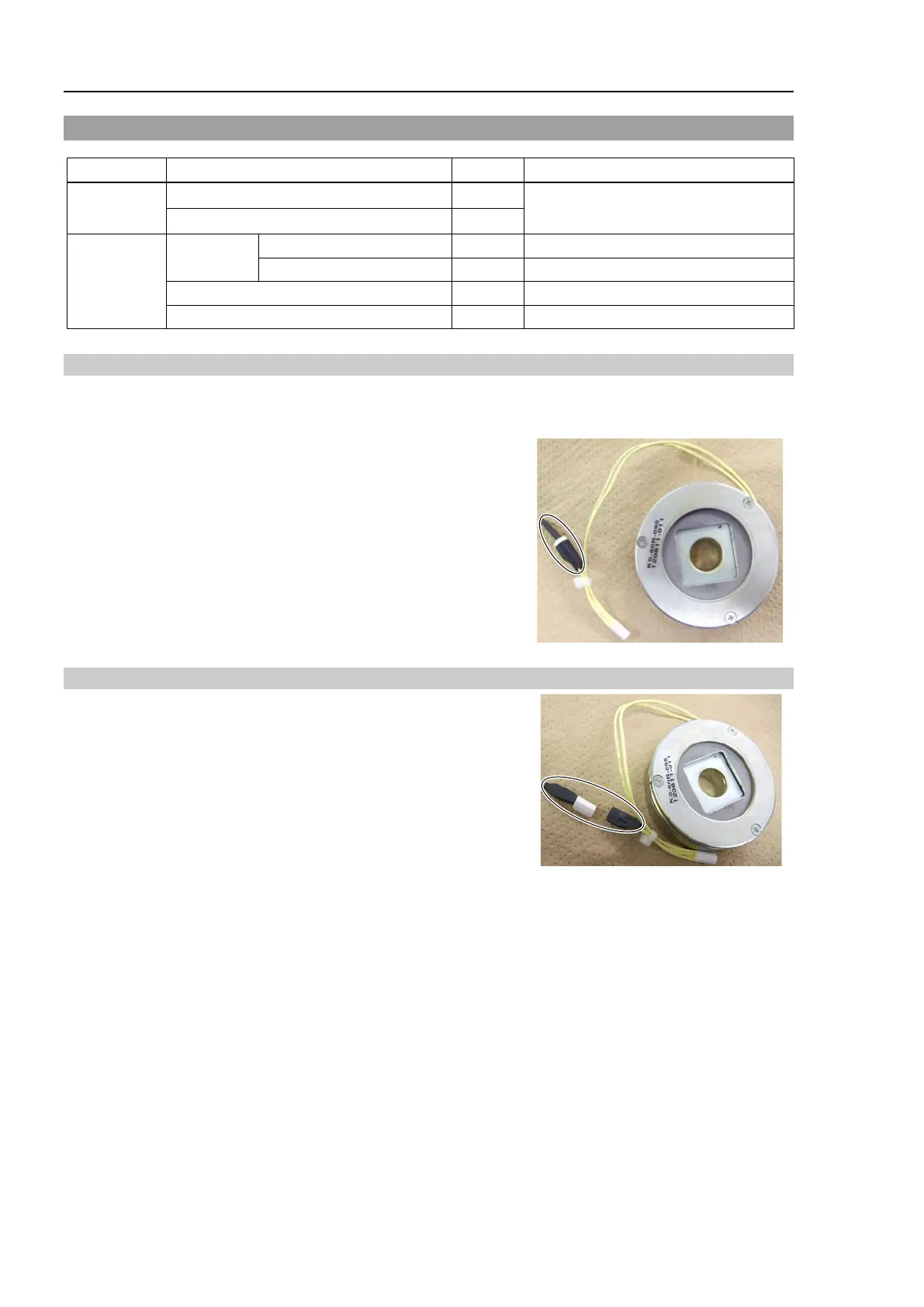
2. Remove the following connector.
Connector: D (for noise dissipative diode)
Installation: Joint #1 Electromagnetic brake
1.
Install the following connector to the connector of the
electromagnetic brake.
Connector: D (for noise dissipative diode)
2. Mount the Joint #1 motor unit.
For details, refer to C4 Maintenance: 5.1 Joint #1 motor, Installation step (2) to (9).
 Loading...


