EPSON Stylus C110/C120/D120 Revision B
DISASSEMBLY/ASSEMBLY Disassembling Printer Mechanism 100
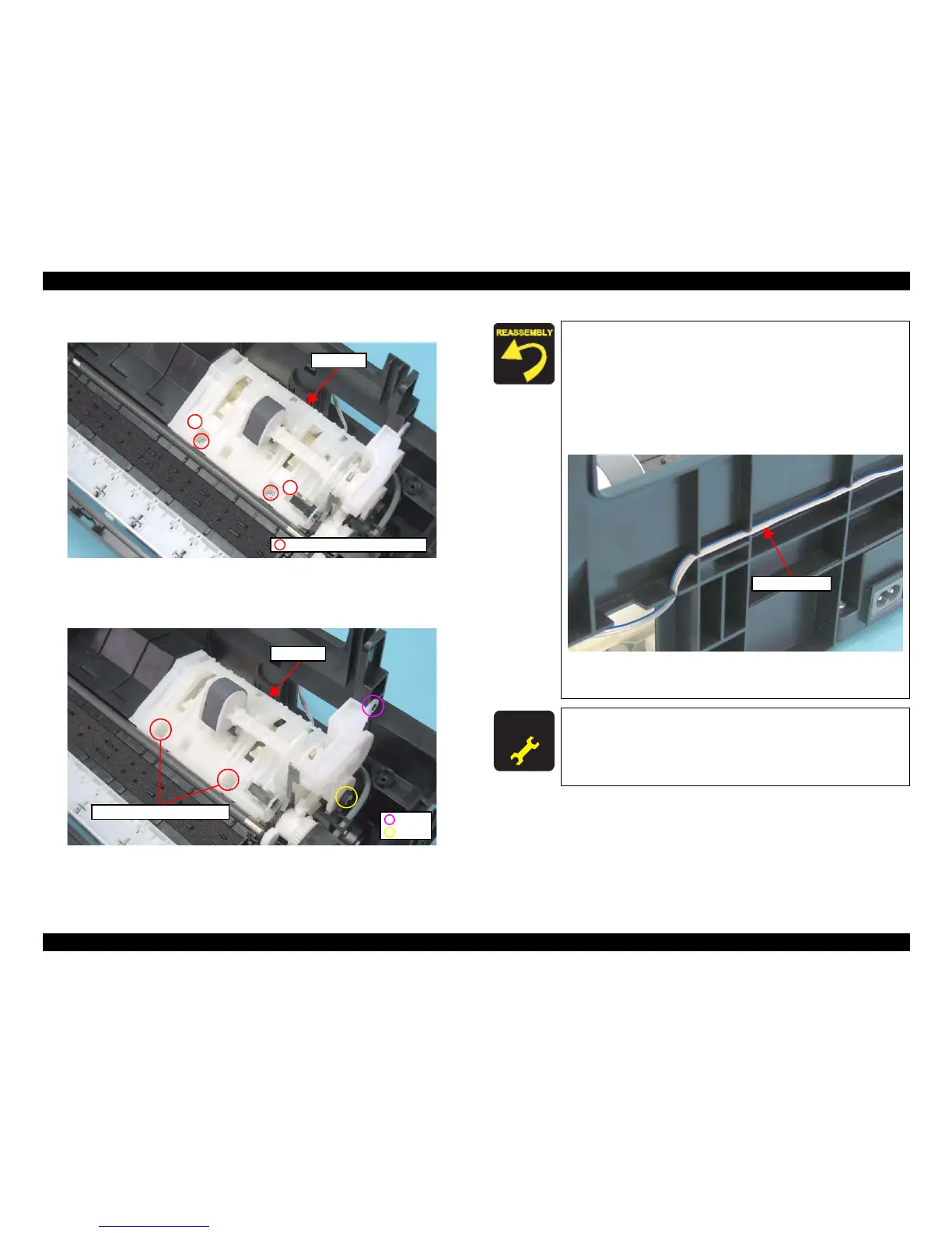
2. Remove the screws (x2) that secure the ASF Unit.
Figure 4-70. Removing ASF Unit (1)
3. Release the guide pins (x3) of the Base Frame and the shaft (x1) of the ASF Unit,
and then remove the ASF Unit.
Figure 4-71. Removing ASF Unit (2)
C.B.P. 3x8, F/Zn-3C (6±1kgfcm)
ASF Unit
1
2
ASF Unit
Dowel
Shaft
Guide Pin and Positioning Hole
When installing the ASF Unit, be sure to align the guide pins
(x2) of the Base Frame with the positioning holes (x2) of the
ASF Unit shown in the
Figure 4-70.
When routing the PE Sensor cable, pay attention to the
following instructions.
• Route the cable in the order given in Figure 4-68.
• Make sure to face the blue line of the cable toward the Base
Frame.
Figure 4-72. Routing PE Sensor Cable
• Check if there is no slack in the cable.
A D J U S T M E N T
R E Q U I R E D
After removing/replacing the ASF Unit, be sure to perform the
specified adjustment. See
Chapter 5 “ ADJUSTMENT”
(p.107)
After replacing the ASF Unit, be sure to perform the required
lubrication. See
Chapter 6 “ MAINTENANCE” (p.116)
 Loading...