EPSON Stylus C110/C120/D120 Revision B
DISASSEMBLY/ASSEMBLY Disassembling Printer Mechanism 95
4.5.12 Main Frame Assy.
Part/Unit that should be removed before removing Main Frame Assy.
Upper Housing/Lower Housing/Main Board Unit/Left Frame/Panel Unit/Front
Frame/Right Frame/CR Motor/CR Scale/Hopper
Removal Procedure
1. Remove the Grounding Spring from the PF Motor.
(Refer to 4.5.10 PF Motor Step2 (p91))
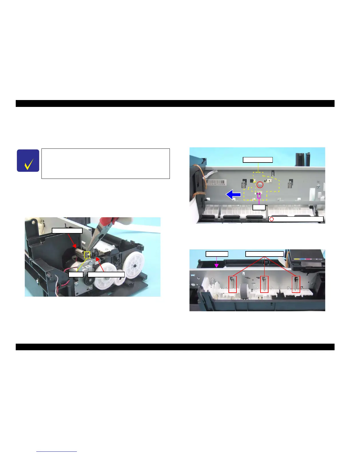
2. Release one end of the Extension Spring from the hook of the Main Frame with a
longnose plier, and then remove the spring together with the Driven Pulley Holder.
Figure 4-56. Removing Extension Spring and Driven Pulley Holder
3. Move the CR Unit to left side of the printer.
4. Remove the screw (x1) that secures the LD Shaft Holder.
5. Move the LD Shaft Holder in the direction of the arrow while holding down its tab
with a flathead precision screwdriver, and remove the LD Shaft Holder.
Figure 4-57. Removing LD Shaft Holder
6. Remove the Extension Springs 10.99 (x3) from each hook of the Main Frame and
the Upper Paper Guide.
Figure 4-58. Removing Upper Paper Guide (1)
 Loading...