EPSON Stylus C110/C120/D120 Revision B
DISASSEMBLY/ASSEMBLY Disassembling Printer Mechanism 96
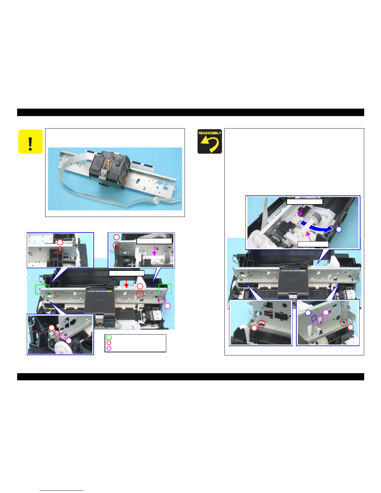
7. Remove the screws (x6) that secure the Main Frame, and remove it while avoiding
the LD Roller Shaft so as not to hit the Upper Paper Guide.
Figure 4-60. Removing Main Frame Assy.
When laying the Main Frame Assy, make sure to put it as shown in the
figure below. Do not lay it with the rollers of the Upper Paper Guide
facing downward, or the rollers or the nozzle surface may get damaged.
Figure 4-59. Precaution on Handling Main Frame Assy.
C.B.S. 3x6, F/Zn-3C (8±1kgfcm)
Holding Position
C.B.P. 3x8, F/Zn-3C (6±1kgfcm)
Main Frame Assy.
1
6
When installing the Main Frame Assy, pay attention to the
following instructions.
1. Put the right part of the Upper Paper Guide indicated in
the figure below under the LD Roller Shaft.
2. Align the hook (x1) of the Frame Support with the positioning
hole (x1) of the Main Frame.
3. Align the hook (x1) of the ASF Unit with the positioning hole
(x1) of the Main Frame.
4. Align the guide pins (x2) of the Base Frame with the
positioning holes (x2) of the Main Frame.
Figure 4-61. Installing Main Frame Assy.
LD Roller Shaft
Upper Paper Guide
1
 Loading...