EPSON Stylus C110/C120/D120 Revision B
OPERATING PRINCIPLE Electrical Circuit Operating Principles 36
2.3.2 C687 Main Board
The logic circuit of the C687 main board consists of the following components.
Logic line
(CPU-ASIC, SDRAM, FlashROM, etc.)
Motor control/drive circuit (CR motor/PF motor)
Head control/drive circuit
USB Interface control circuit
Sensor circuit
Reset circuit, EEPROM circuit
The printer mechanism is controlled by the above circuits. Following describes the
major characteristics of the main board.
Streamlining with no complex circuit
The main board includes the reset circuit and EEPROM circuit independently.
This simple configuration is achieved because RTC is not required for the Stylus
C110/C120/D120, which does not have stand-alone direct print function.
Power save mode
The main board reduces power consumption by carrying out the followings in the
power save mode.
Partially stops the ASIC clock
Brings the motor driver/head DAC into sleep/standby mode
Stops energizing motors
Brings the SDRAM into the self-refresh mode
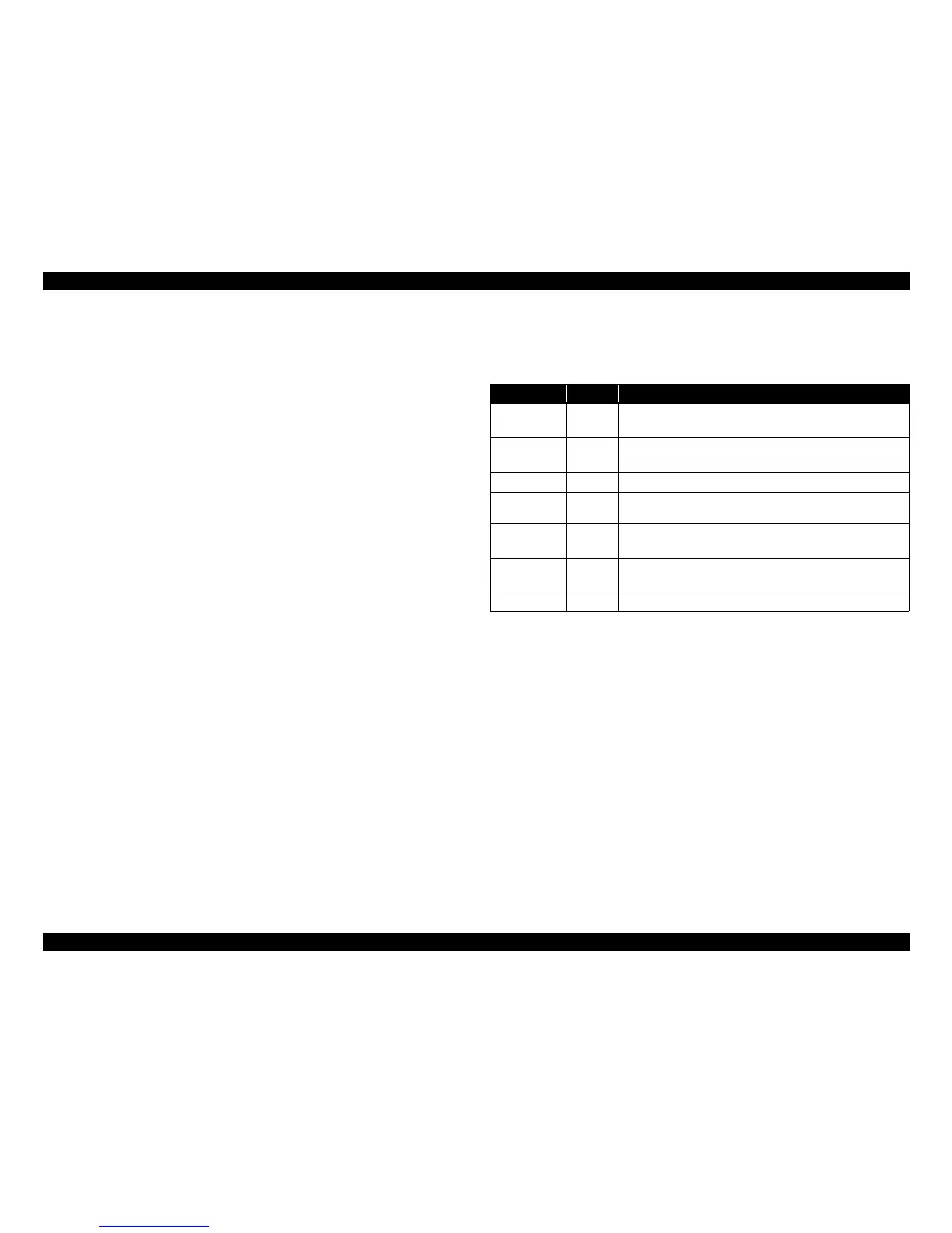
2.3.2.1 Major Components on Main Board
The table below lists the major components on the C687 main board.
Table 2-6. Major Components on Main Board
IC Location Function
Flash ROM IC1
4Mbit
• Stores the firmware
SDRAM IC2
64Mbit
• bus: 16bit
Reset IC IC3 Monitors voltage on 42V line and 3.3V line.
CPU-ASIC IC8
Drives at 96MHz (internal)/48MHz (external) of clock frequency
and controls the printer mechanism, SDRAM and USB.
EEPROM IC9
2kbit
• Stores various mechanical settings
Motor driver IC5
• CR/PF motor drive IC
• Reduces 42V line to 3.3V/1.5V
Head driver IC13 DAC that generates printhead drive waveform
 Loading...