EPSON Stylus C110/C120/D120 Revision B
OPERATING PRINCIPLE Overview 22
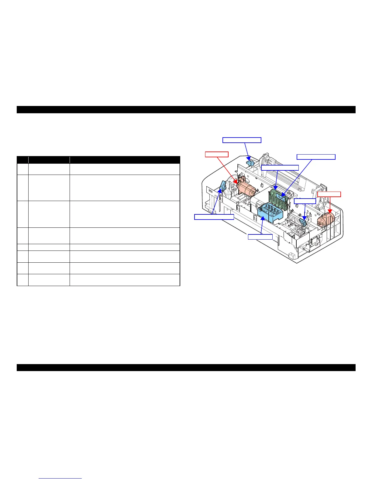
2.1.2 Motors & Sensors
Stylus C110/C120/D120 printer mechanism is equipped with the following printhead,
motors and sensors.
Figure 2-3 shows their locations.
Note " * " : The No.1 nozzle of each color is used only for executing flushing, and is not used for
printing.
Figure 2-2. Motors & Sensors in Printer Mechanism
Table 2-1. List of Motors & Sensors
No. Name Specification
1 Printhead
F3-3 MACH Turbo2 head
(Black: 180 nozzles x 2, Color: 180 nozzles (60 nozzles* x 3 colors) x 1
2 CR Motor
Type: DC motor
Drive voltage: 42VDC +/- 5% (DRV IC voltage)
Characteristics: Coil resistance: 22.7Ω +/- 10%
Inductance: 15.9mH (1KHz)
Drive method: PWM, constant-current chopping
3 PF Motor
Type: DC motor
Drive voltage: 42VDC +/- 5% (DRV IC voltage)
Characteristics: Coil resistance: 21.2Ω +/- 10%
Inductance: 17.2 mH (1kHz)
Drive method: PWM, constant-current chopping
4 PE Sensor
Purpose: Detection of paper top and bottom edge, for control to set
paper at the print start position
Type: Photo interrupter
5 CR contact module CSIC board
6 CR Encoder Sensor
Type: Photo interrupter
Resolution: 180 pulse/inch
7 PF Encoder Sensor
Type: Photo interrupter
Resolution: 180 pulse/inch
8 Cover Open Sensor
Purpose: Detection of open/close status of the printer cover
Type: Mechanical contact
 Loading...