EPSON Stylus C110/C120/D120 Revision B
DISASSEMBLY/ASSEMBLY Disassembly Procedures 72
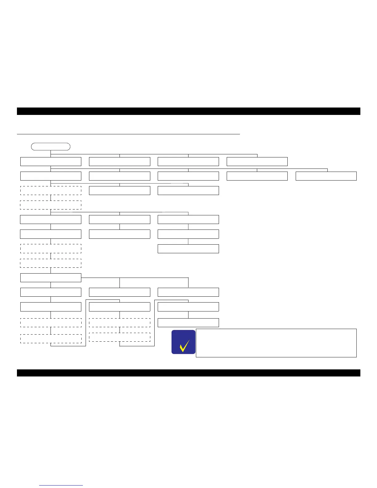
4.2 Disassembly Procedures
For disassembling each unit, refer to the pages in the following flowchart.
Figure 4-1. Disassembling Flowchart
Some parts/units are shown both in the solid line box and the dashed line box. Find the part or
unit you want to remove from those indicated in solid line box (the way to the solid line box is the
shortest way). You need to remove the parts/units shown in dashed line box if they exist on the
way to the target part/unit.
“ 4.3.3 Cover Printer ” (p74)
“ 4.3.1 Paper Support Assy. ” (p73)
“ 4.4.2 Panel Unit ” (p79)
“ 4.4.3 Power Supply Unit ” (p81) “ 4.5.4 Hopper ” (p86)
“ 4.5.14 Upper Paper Guide ” (p99)
“ 4.5.1 Removing Printer
Mechanism (Lower Housing) ” (p82)
“ 4.4.2 Panel Unit ” (p79)
“ 4.5.11 CR Motor ” (p93)
“ 4.5.4 Hopper ” (p86)
“ 4.5.16 Ink System Unit ” (p101)
“ 4.5.6 Star Wheel Holder Assy. ”
(p88)
“ 4.5.9 PF Scale ” (p91)
“ 4.5.18 PF Roller ” (p105)
“ 4.4.1 Main Board Unit/Left
Frame ” (p76)
“ 4.5.15 ASF Unit ” (p99)
“ 4.5.6 Star Wheel Holder Assy. ”
(p88)
“ 4.5.7 EJ Roller ” (p89)
“ 4.3.2 Stacker Assy. ” (p73)
“ 4.3.4 Upper Housing/Cover
Open Sensor ” (p74)
“ 4.5.2 Printhead ” (p83) “ 4.5.3 CR Scale ” (p85)
“ 4.4.1 Main Board Unit/Left
Frame ” (p76)
“ 4.5.7 EJ Roller ” (p89)
“ 4.5.8 PF Encoder Sensor ” (p90) “ 4.5.19 Waste Ink Pads ” (p106)
“ 4.5.5 Front Frame/Right Frame ”
(p87)
“ 4.5.10 PF Motor ” (p91)
“ 4.5.8 PF Encoder Sensor ” (p90)
“ 4.5.9 PF Scale ” (p91)
“ 4.5.17 Front Paper Guide ”
“ 4.5.12 Main Frame Assy. ” (p95)
“ 4.5.3 CR Scale ” (p85)
“ 4.5.13 CR Unit ” (p97)
Start
 Loading...