EPSON Stylus C110/C120/D120 Revision B
DISASSEMBLY/ASSEMBLY Removing Board 81
4.4.3 Power Supply Unit
Part/Unit that should be removed before removing Power Supply Unit
Upper Housing/Lower Housing
Removal Procedure
1. Disconnect the connectors of the Panel Unit FFC (CN11) and the Power Supply
Unit (CN1) from the Main Board. (refer to Figure 4-9)
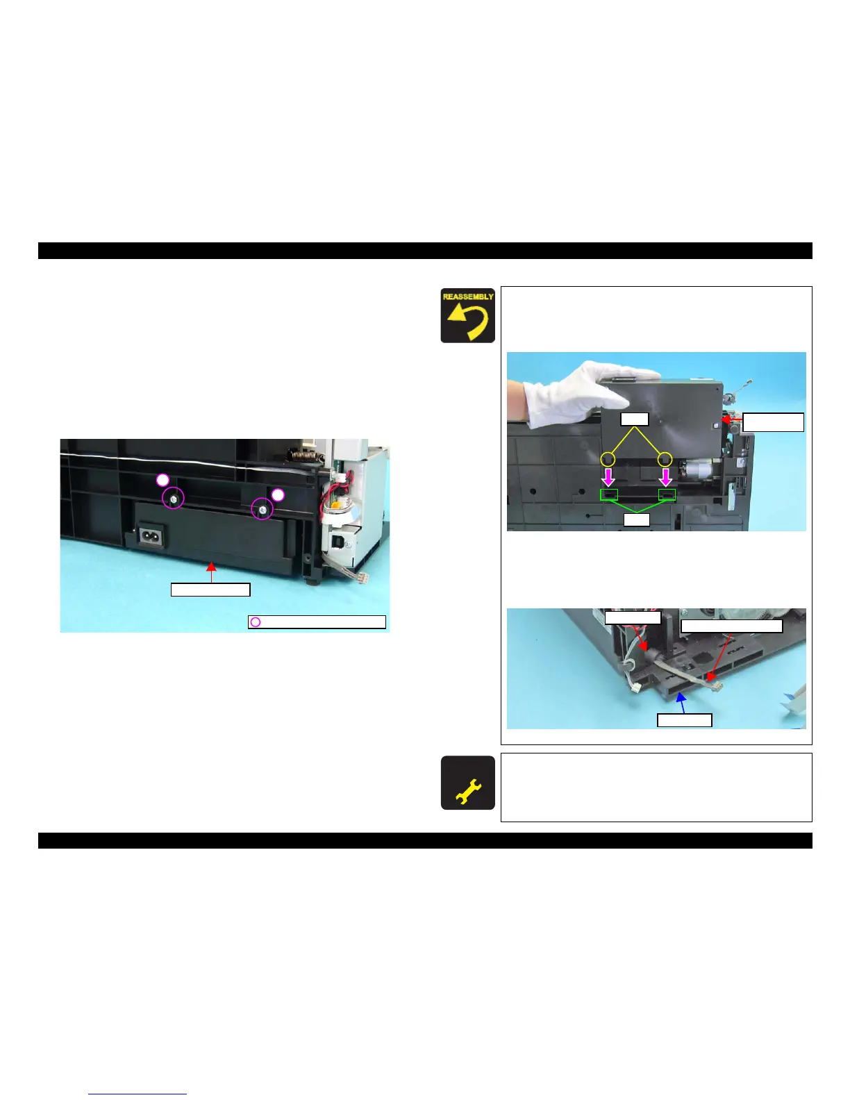
2. Remove the screws (x2) that secure the Power Supply Unit.
3. Lift the Base Frame a little, and then remove the Power Supply Unit.
Figure 4-21. Removing Power Supply Unit
C.B.P. 3x10, F/Zn-3C (6±1kgfcm)
Power Supply Unit
1
2
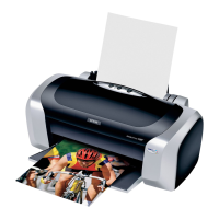
When installing the Power Supply Unit, make sure to check the
following points.
Insert the tabs (x2) of the Power Supply Unit into the holes on
the Base Frame.
Figure 4-22. Installing the Power Supply Unit
Tighten the screws in the order given in Figure 4-21.
Put the ferrite core attached to the Power Supply Unit cable
into the cutout of the Base Frame.
Figure 4-23. Routing the Power Supply Unit Cable
A D J U S T M E N T
R E Q U I R E D
After replacing the Power Supply Unit, be sure to perform
specified adjustment. See
Chapter 5 “ ADJUSTMENT” (p.107)
Power Supply Unit Cable
Base Frame
Ferrite core