EPSON Stylus C110/C120/D120 Revision B
DISASSEMBLY/ASSEMBLY Disassembling Printer Mechanism 106
4.5.19 Waste Ink Pads
Part/Unit that should be removed before removing Waste Ink Pads
Upper Housing/Lower Housing/Main Board Unit/Left Frame/Panel Unit/Front
Frame/Right Frame/CR Motor/CR Scale/Hopper/Main Frame Assy./ASF Unit/Ink
System Unit/Star Wheel Holder Assy./EJ Roller/Front Paper Guide/PF Encoder
Sensor/PF Scale/PF Roller
Removal Procedure
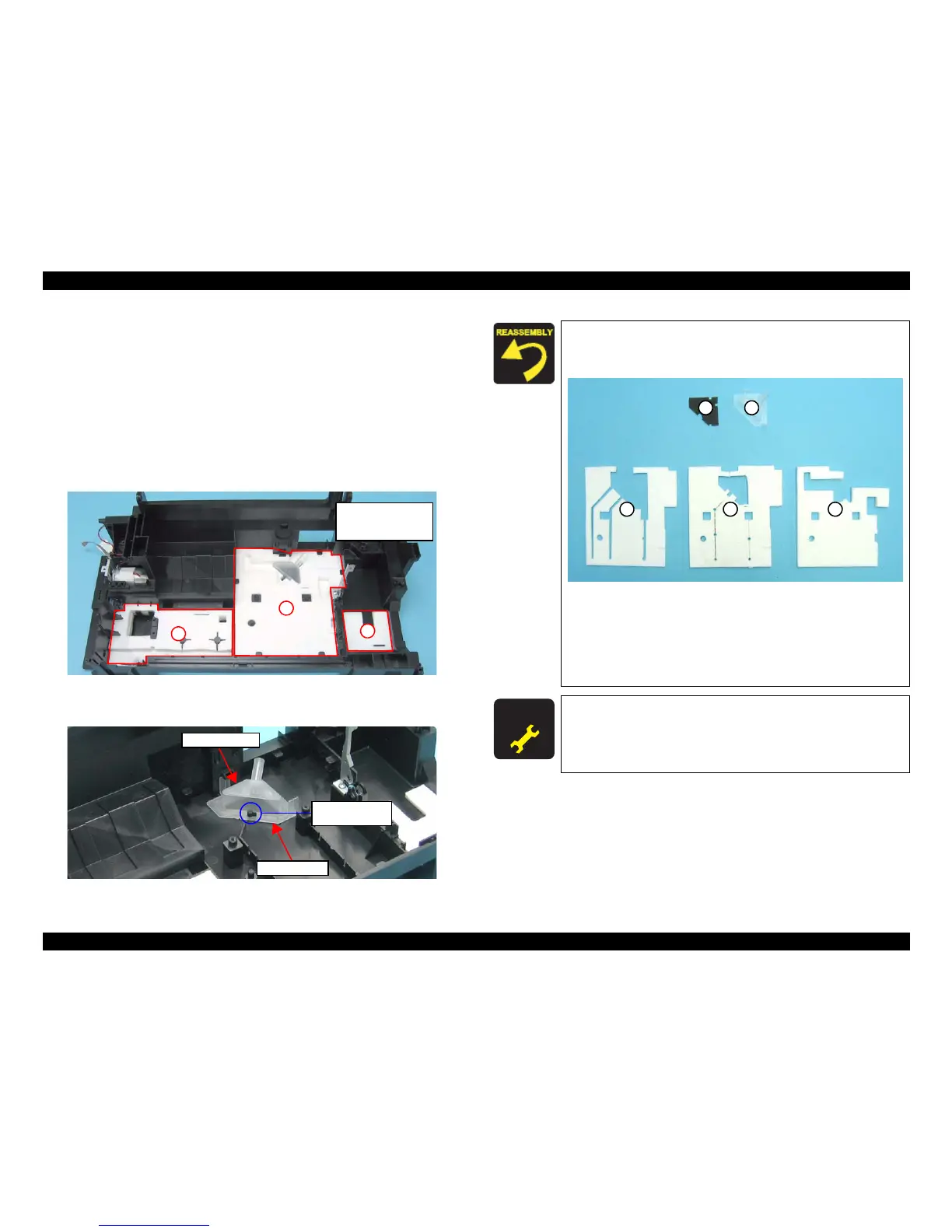
1. Remove the Waste Ink Pads (x6) from the sections indicated with A to C of the
Base Frame.
Figure 4-87. Removing Waste Ink Pads
2. Remove the Waste Ink Cover and the Diffusion Sheet.
Figure 4-88. Removing Waste Ink Cover and Diffusion Sheet
A
B
C
A: Waste Ink Pads x2
B: Waste Ink Pads x3
C: Waste Ink Pads x1
Waste Ink Cover
Diffusion Sheet
Guide Pin and
Positioning Hole
When installing the Diffusion Sheet, Waste Ink Cover, and the
Waste Ink Pads (x3) on section B, attach them in the order
given in the figure below
.
Figure 4-89. Installing Waste Ink Pads
When installing the Waste Ink Cover, be sure to align the
guide pin (x1) of the Base Frame with the positioning hole (x1)
of the Waste Ink Cover. Make sure the cover is properly
secured on the Diffusion Sheet without any gaps as shown in
Figure 4-88.
A D J U S T M E N T
R E Q U I R E D
After replacing the Waste Ink Pads, be sure to perform specified
adjustment. See
Chapter 5 “ ADJUSTMENT” (p.107)
 Loading...