4 INSTALLATION
0463 613 101
- 15 -
© ESAB AB 2020
• Make sure the column is in the locked position (1), directed forward as shown in the
illustration.
• Make sure the welding head arm is in the locked position (2).
• Remove the bobbin holder or the wire drum from the bobbin holder. Make sure that the
empty bobbin holder is in the locked position (3).
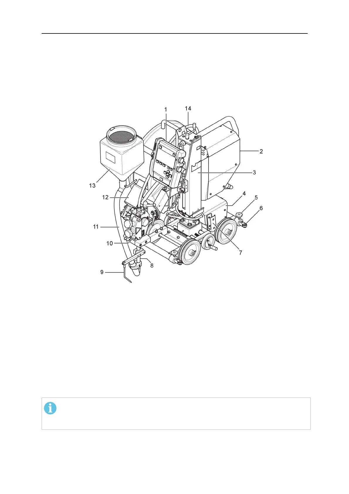
4.3 Main components
1. EAC10 Control pendant 8. Contact tube
2. EAC10 Motor drive unit 9. Guide pin
3. Column 10. Wire feed unit
4. Tractor carriage 11. Flux tube
5. Guide bar lock 12. Wire feed motor
6. Guide bar 13. Flux hopper
7. Cable support 14. Wire liner
4.3.1 Welding cables
Use a different number of welding cables for different welding currents:
Up to 500A
one 120-mm
2
cable
500–1000A
two 120-mm
2
cables
NOTE!
With a two welding cable setup, run the welding cables close to each other in
parallel, but do not twist them around each other.
4.4 Assembly
For information about assembly of the welding tractor, see chapter "Transportation."
 Loading...