427-0073-12-12 Version 120 May 2015 1-7
1
Camera Installation
1.6 Camera Connections
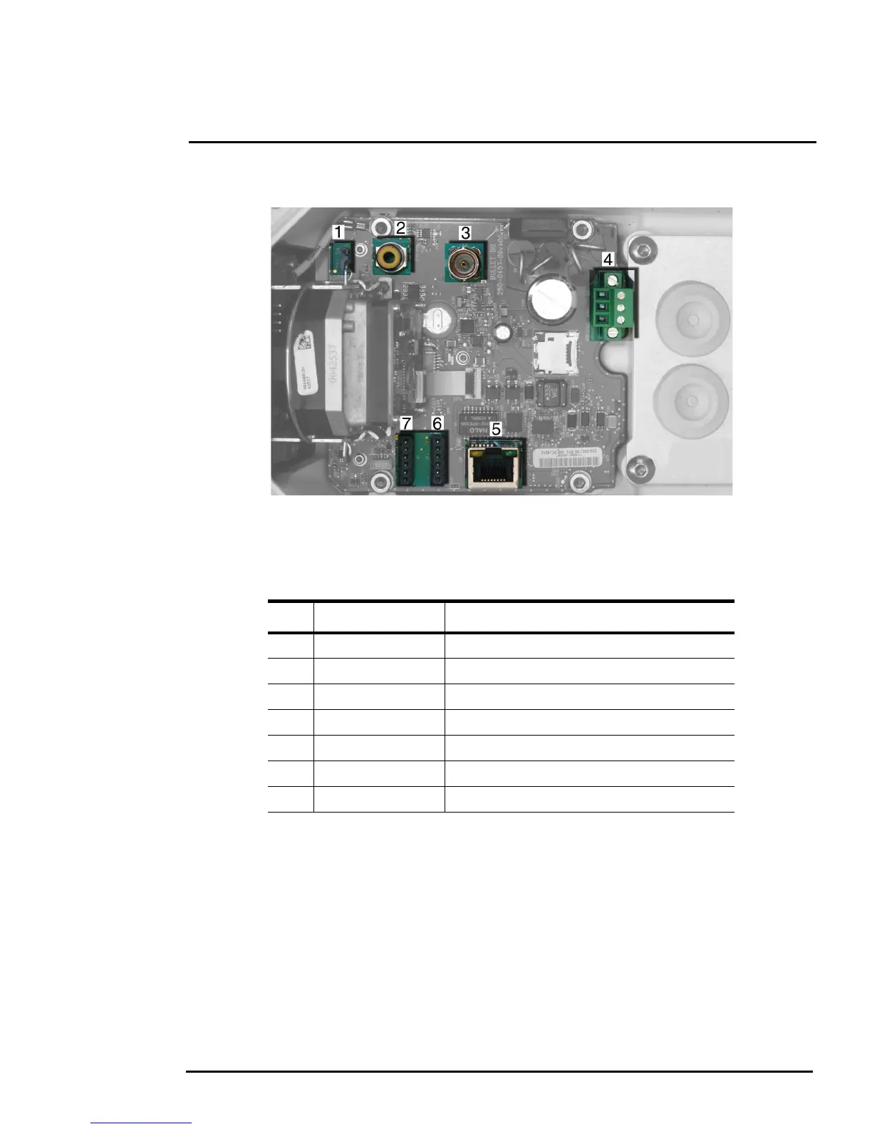
Refer to Table 1-1 for a description of these camera connections.
1.6.1 Prior to Cutting/Drilling Holes
When selecting a mounting location for the FC-Series camera, consider cable lengths and cable
routing. Ensure the cables are long enough, given the proposed mounting locations and cable routing
requirements, and route the cables before installing the components.
Use cables that have sufficient dimensions to ensure safety (for power cables) and adequate signal
strength (for video and communications).
Table 1-1: FC-Series Camera Connections
Connection Purpose
1 3-pin Jumper Supplemental lens heater on/off
2 RCA Analog video test point
3 BNC Analog video
4 3-pin Terminal ac/dc power
5 Ethernet PoE+ power, communications, IP video stream
6 6-pin terminal J8 General purpose I/O
7 Accessory inputs Reserved for future use
Figure 1-7: Camera Connections
 Loading...