427-0073-12-12 Version 120 May 2015 1-10
1
Camera Installation
1.6.7 GPIO Connections
Input Signal—The camera can receive an external
input signal on accessory connector J8 pins 4 and 5
when these pins are connected by an external
switch closure. Pin 5 is connected to the camera’s
internal +5V power supply and must not be directly
connected to chassis ground. Pin 4 is connected to
the internal digital ground.
While protection for static discharge has been
placed on these pins, care should be used in
making connections to the pins to avoid
connections to other voltages or power sources
outside the camera.
Output Signal—The camera can provide a contact closure output on accessory connector J8 pins 2
and 3 when an external voltage is supplied to these pins. When open the resistance between pins 2
and 3 is greater than 100 K ohm. When closed the resistance between pins 2 and 3 is less than 200
ohm. The maximum recommended peak voltage between the pins is 6 volts. The maximum
recommended current allowed between the pins is 30 mA (0.03 A).
Note
Table 1-3: GPIO Connections - J8
Pin Connection Notes
1 Chassis ground
2 GPIO Out When the camera sends an output signal, an
external voltage on one pin is applied to the
other pin.
3 GPIO Out
4 Digital ground
When these pins are connected externally,
the camera reads this as an input signal.
5 +5V
6 Chassis ground
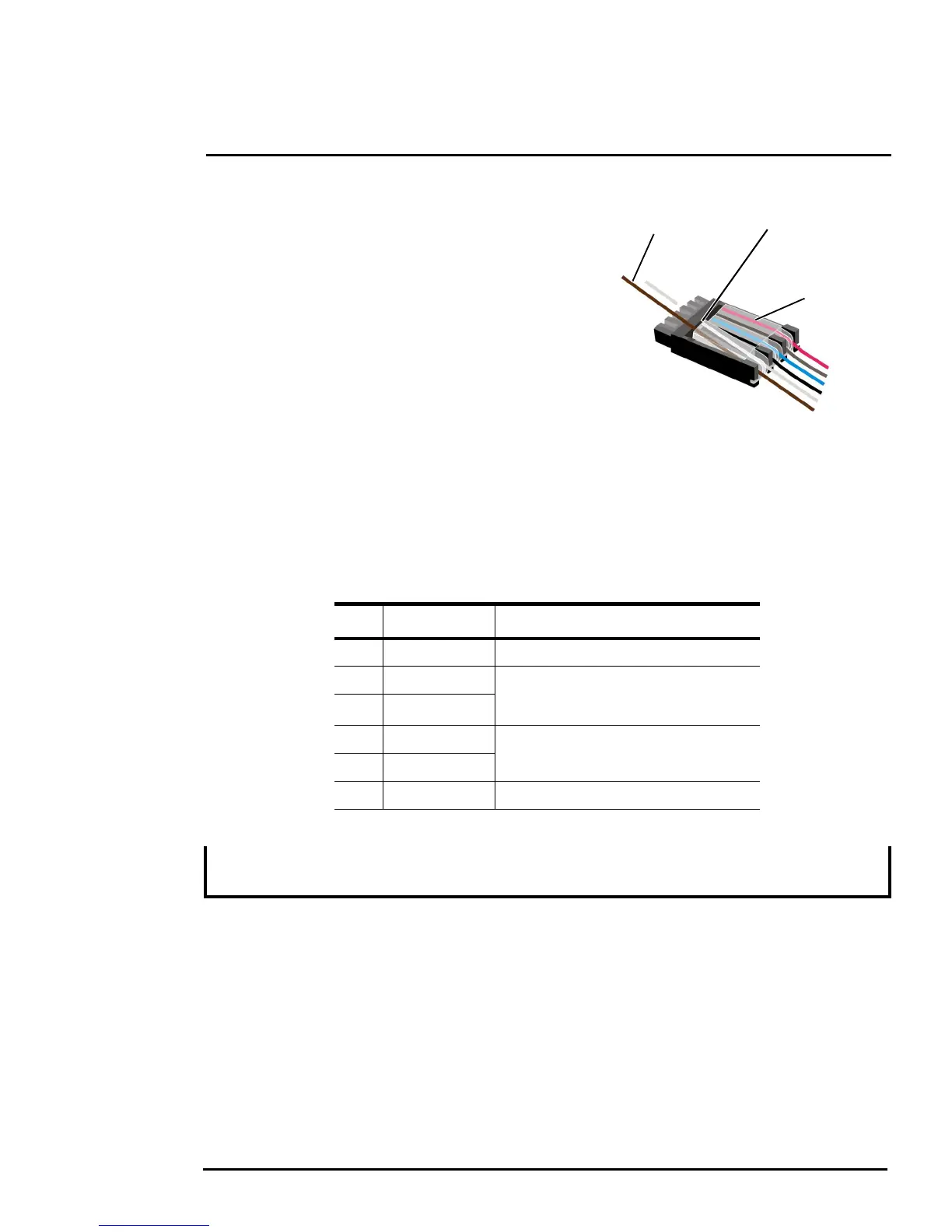
The terminal plug supplied for GPIO connections uses stranded 26 AWG wire size (1 mm diameter
including insulation) using spring-cage and pierce contact technology.
Figure 1-13: GPIO and Ethernet Connectors
pin 1
1. Insert wires 2. Snip wire
through plug and close cage

 Loading...