427-0089-00-12 Version 160 March 2019 15
This document does not contain any export-controlled information.
Camera Installation
The power cable supplied by the installer must use wires that are sufficient size gauge for the supply
voltage and length of the cable run to ensure adequate current carrying capacity (18 AWG
recommended for most installations). Always follow local building/safety codes.
Note
The power connector plug may be removed for cable installation. After the plug is reattached to the
board, re-tighten the screw terminals.
The camera itself does not have an on/off switch. Generally the FC-Series camera may be
connected to a circuit breaker and the circuit breaker will be used to apply or remove power to the
camera. If power is supplied to it, the camera will be powered on and operating.
1.4.5 GPIO Connections
Input Signal—When the camera senses an external
switch closure which completes the circuit between
J5 pins 4 and 5, an input signal is generated by the
GPIO for the Alarm Manager. Refer to Alarm
Manager, pg. 62.
Output Signal—Accessory connector J5 pins 2 and
3 connect to a switch in the camera to complete the
circuit for the receiving device. When open the
resistance between pins 2 and 3 is greater than 100 K
ohm. When closed the resistance between pins 2 and
3 is less than 200 ohm. The maximum recommended peak voltage between the pins is 6 volts. The
maximum recommended current allowed between the pins is 30 mA (0.03 A).
By default the GPIO alarm circuits are configured for normally open switches, to configure a GPIO
alarm circuit for a normally closed switch, refer to Devices Menu GPIO, pg. 60.
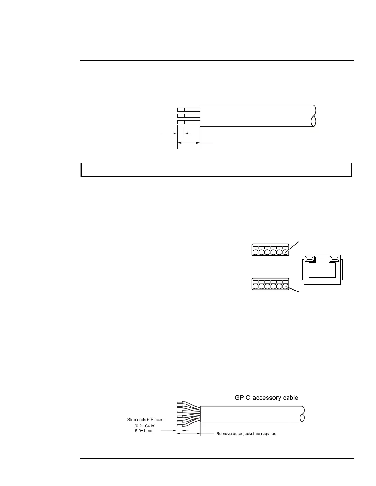
The terminal plug supplied for GPIO connections may be either a fast connect, spring-cage and
pierce contact, or a push-in spring contact.
The push-in spring contact accepts 20 - 24 AWG conductors. Strip conductor ends to 6 mm.
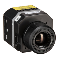
The terminal connector for power connections will accept 16 AWG to 24 AWG wire size.
(0.8±.20 in)
20.0±5 mm
Remove outer
jacket
(0.2±.04 in)
6.0±1 mm
Strip ends
3 Places
Power Cable
Figure 1-9: GPIO and Ethernet
Connectors
J3 pin 1
J5 pin 1
Ethernet

 Loading...