427-0089-00-12 Version 160 March 2019 60
This document does not contain any export-controlled information.
Advanced Configuration
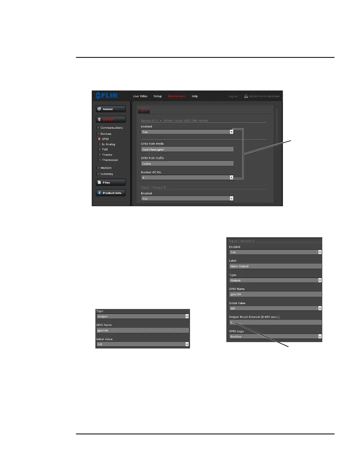
Devices Menu GPIO: On the GPIO page, scroll down to read the current I/O parameters. GPIO is
enabled by default.
The GPIO must be wired during installation, refer to GPIO Connections, pg. 15. The status of the
GPIO signals are displayed on the Temperature page from the Setup menu, refer to Temperature
Page, pg. 43.
The illustration at the right shows the default
settings for the output signal channel, Input/Output
0.
• The Label setting can be changed to reflect
more specific alarm information which can then
appear in VMS systems such as FLIR Latitude.
• The GPIO Name determines the circuit point for
the GPIO driver and must not be changed. Set
an Initial Value (On or Off) for this output signal.
• The Output Reset Interval is used to
automatically reset the output signal after a set
time. Setting the value to 0 prevents the output
from resetting automatically after a timeout. See
also the Alarm Manager GPIO Output State
Mode parameter, GPIO Output from Motion
Alarm, pg. 66.
• Set Alarm Output GPIO Logic to Positive for a normally open switch signal (circuit closes for
alarm), Set GPIO Logic to Negative for a normally closed switch signal (circuit opens for alarm).
Default
Settings
Output duration

 Loading...