427-0089-00-12 Version 160 March 2019 16
This document does not contain any export-controlled information.
Camera Installation
The spring-cage and pierce contact accepts 22 AWG to 24 AWG, stranded conductors with a 1.6 mm
maximum diameter including insulation. Do not strip insulation from conductors.
Caution!
1.4.6 Ethernet
Connect a shielded Cat5e or Cat6 Ethernet cable to the RJ-45 jack. If using PoE+ to supply power to
the camera, connect the other end of the cable to a PoE+ switch or PoE+ injector. Otherwise
connect the cable to a network switch.
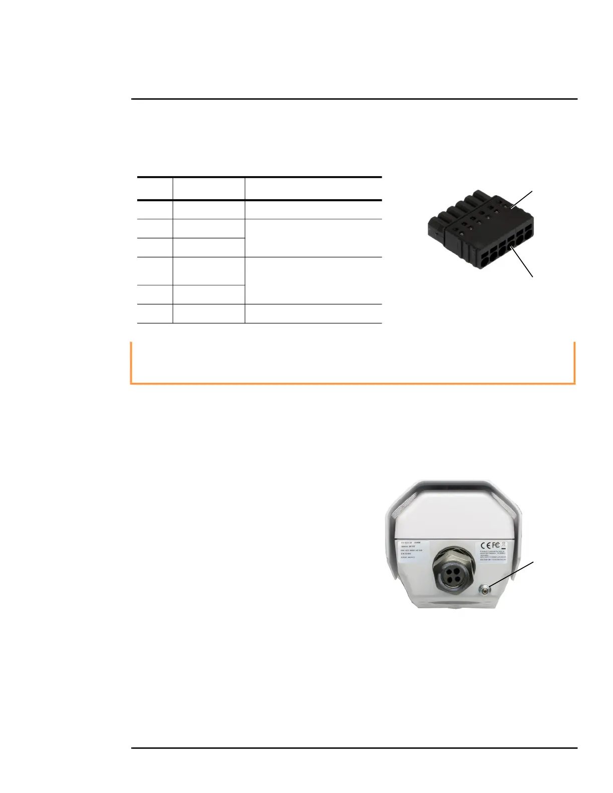
1.4.7 Camera Grounding
Ensure the camera is properly grounded. Failure to
properly ground the camera can lead to permanent
damage to the camera. Typical to good grounding
practices, the camera chassis ground should be
connected to the lowest resistance path possible. The
camera has an external ground connection on the
outside back of the camera. FLIR requires a
grounding strap anchored to the grounding lug and
connected to the nearest earth-grounding point.
If, during installation, any ground connections inside
the camera are disconnected, they should be
reconnected prior to closing the camera.
J5 pins 4 and 5 must not be connected to outside voltages or power sources. Pin 5 must not be
connected to chassis ground. While protection for static discharge has been placed on these pins,
care should be used when making connections to avoid damage to the camera.
Figure 1-10: GPIO Terminal Plug
Pin 1
Insert wires
Table 1-3: GPIO Connections - J5
Pin Connection Notes
1
Chassis ground
2
GPIO Out
When the camera sends an output
signal, an external voltage on one
pin is applied to the other pin.
3
GPIO Out
4
GPIO In2
(Digital ground)
When these pins are connected
externally, the camera reads this as
an input signal.
5
GPIO In1 (+5V)
6
Chassis ground
(Push-in spring contact)
Figure 1-11: Camera Ground
Ground

 Loading...