427-0089-00-12 Version 160 March 2019 6
This document does not contain any export-controlled information.
Camera Installation
1.3 Installation Overview
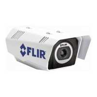
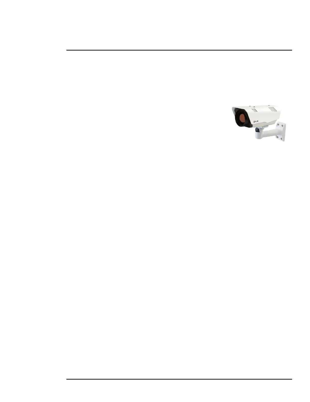
The FC-Series camera is an infrared thermal imaging camera intended for outdoor security
applications, and can be installed in a fixed location or on a pan/tilt mechanism. The camera is
intended to be mounted on a medium-duty fixed pedestal mount or wall mount commonly used in the
security industry. The camera mount must support up to 5.4 lbs (2.5 kg).
Cables may exit from the back of the camera housing through the
supplied cable gland or from the bottom of the camera housing when
using the concealed cable wall mount (sold separately). A cable gland
plug is supplied for the rear of the camera housing when cables are
routed using the concealed cable wall mount.
1.3.1 Camera Connection Options
The camera can be installed with an analog or digital (IP) video output (or both). Analog video will
require a connection to a video monitor or an analog video matrix switch. The camera can be
powered using Power over Ethernet Plus (PoE+) or with a conventional 24 Vac or 24 Vdc power
supply. For a PoE+ connection, an accessory PoE+ power supply (PN 4132391, also called a PoE+
injector) is available if the camera is not connected to a PoE+ switch. The maximum Ethernet cable
run is 100 meters including the PoE+ power supply. In installations using PoE+ power and IP video,
only a single Ethernet cable from the camera is required.
In installations using analog video and conventional power (24 Vac is commonly used in many
installations), an RG59U coaxial cable and a three-conductor power cable are installed. It is
recommended an Ethernet cable should also be installed for camera configuration, operation and
troubleshooting. For example, if the camera is mounted on a pole, an Ethernet cable should run at
least to the bottom of the pole, so a laptop could be temporarily connected directly to the camera.
The FC-Series camera does not support serial communications.
Network Security
The camera supports IEEE 802.1x authentication when connected to a network supporting the
following requirements:
• Network device (Authenticator) such as an Ethernet switch configured with 802.1x
• Authentication server supporting TLS
Refer to IEEE 802.1X Security, pg. 29 for information on how to configure the LAN settings.
General Purpose Input/Output (GPIO)
The camera can receive a single input signal and can provide a single output signal. By default the
signals are configured for normally open alarm switch circuits. Refer to GPIO Connections, pg. 15.
Input Signal—When an external alarm device closes a switch to complete the circuit for the
camera, an input alarm is generated by the GPIO for the Alarm Manager.
Output Signal—When an output alarm is generated by the Alarm Manager for the GPIO, the
camera closes its internal switch to complete the circuit for the receiving device.

 Loading...