427-0089-00-12 Version 160 March 2019 17
This document does not contain any export-controlled information.
Camera Installation
1.4.8 Rear Access Cable Gland Sealing
Proper installation of cable sealing gland and use of appropriate elastomer inserts is critical to long
term reliability. Cables enter the rear of the camera mount enclosure through a liquid-tight
compression gland.
Leave the gland nut loosened until all cable installation has been completed, and ensure the
manufacturer’s recommended cable bend radius is observed within the enclosure. Do not forget to
tighten the cable gland seal nut to ensure a watertight seal and provide strain relief for cables.
Cable Gland Seal Inserts
The FC-Series camera comes with a single 3/4” NPT cable gland installed in the enclosure, with a
four-hole gland seal insert. The gland includes a sealing washer and is secured to the camera with a
nut on the inside of the enclosure. The gland insert has one hole for the RG-59/U analog video cable
(the larger hole) and three more for a power cable, Ethernet cable, and an accessory cable.
Any of the holes which are not used for cables should be filled with one of
the hole plugs (supplied). Install the cables through the cable gland so that
the cables line up with the connections inside the camera.
Note
To ensure a water tight seal when using the supplied rear cable gland, cable dimensions must be
within the minimum and maximum as described in Table 1-3.
Table 1-3: Rear Exit Cable Min/Max Dimensions
Cable Min Max
Power (3 conductor),
Ethernet, Accessory cables
4.5 mm
[0.178 in]
5.2 mm
[0.205 in]
RG 59 Video cable
5.3 mm
[0.209 in]
6.2 mm
[0.244 in]
Insert the cables through the cable glands on the enclosure before terminating and connecting them.
In general, terminated connectors will not fit through the cable gland. If a terminated cable is
required, make a clean and singular cut in the gland seal to install the cable into the gland seal.
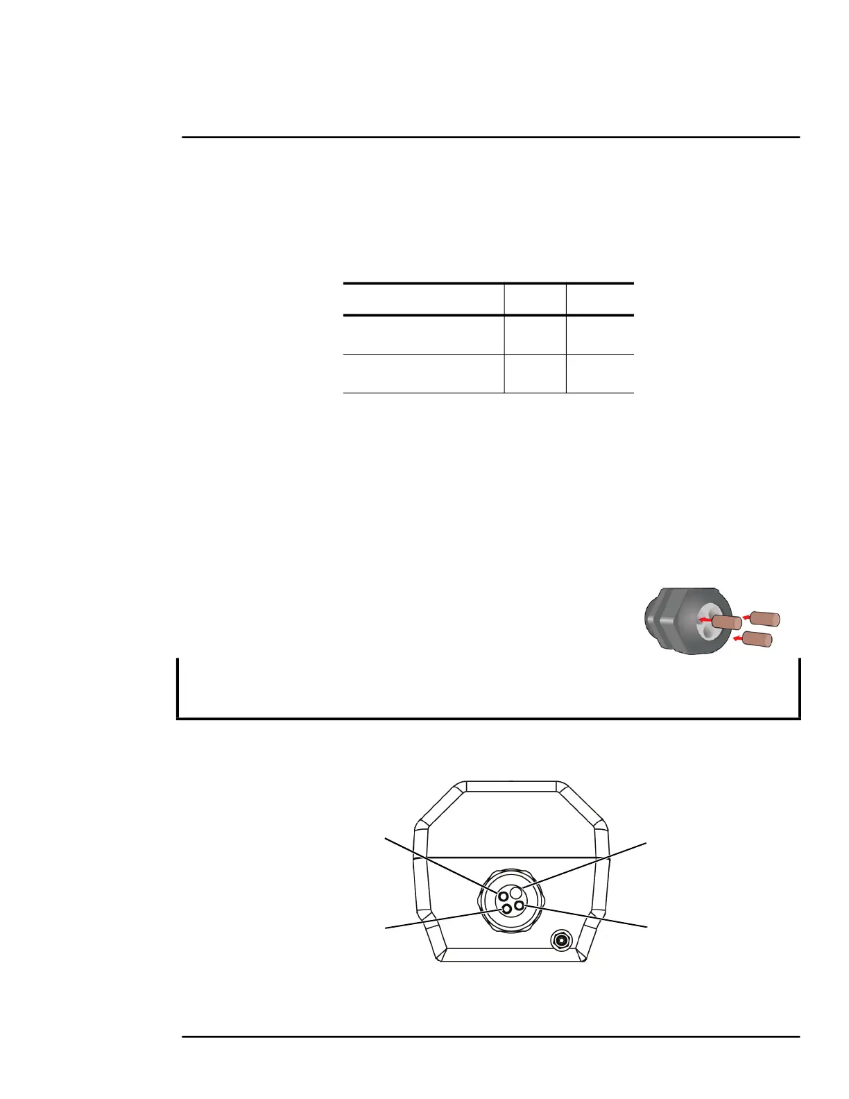
Figure 1-12: Cable Routing
Power Cable
Video Cable
Accessory cable
Ethernet
RG 59 coaxial
3 Conductor

 Loading...