10-2
10.3 Compliance with EMC Standards
10.3.1 General
The CE marking on inverters does not ensure that the entire equipment including our CE-marked
products is compliant with the EMC Directive. Therefore, CE marking for the equipment shall be
the responsibility of the equipment manufacturer. For this reason, Fuji’s CE mark is indicated under
the condition that the product shall be used within equipment meeting all requirements for the
relevant Directives. Instrumentation of such equipment shall be the responsibility of the equipment
manufacturer.
Generally, machinery or equipment includes not only our products but other devices as well.
Manufacturers, therefore, shall design the whole system to be compliant with the relevant
Directives.
In addition, to satisfy the requirements noted above, use a Fuji FRENIC inverter in connection with
an EMC-compliant filter (optional feature) in accordance with the instructions contained in this
instruction manual. Installing the inverter(s) in a metal enclosure may be necessary, depending
upon the operating environment of the equipment that the inverter is to be used with.
Our EMC compliance test is performed under the following conditions.
- Motor Sound (carrier frequency) (F26): 15 kHz
- Wiring length (of the shielded cable) between the inverter and motor: 33ft (10 m)
10.3.2 Recommended installation procedure
To make the machinery or equipment fully compliant with the EMC Directive, have certified
technicians wire the motor and inverter in strict accordance with the procedure described below.
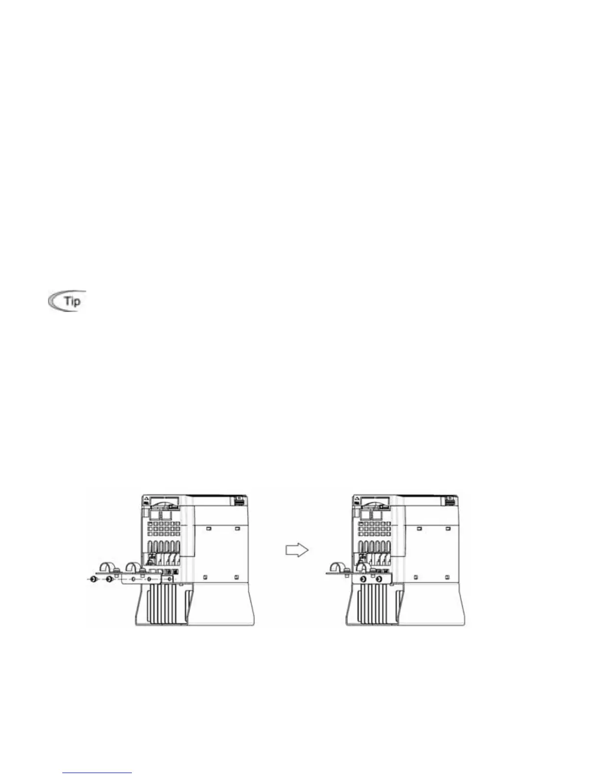
In the case of EMC filter built-in type of inverters with a capacity of 5 HP or below
1) Mount the EMC grounding flange (that comes with the inverter) to the inverter with screws in
order to ground the wire shield(s). (See Figure 10.1.)
Figure 10.1 Attaching the EMC Grounding Flange
2) Use shielded wires for the motor cable and route it as short as possible. Firmly clamp the wire
shield to the flange to ground it. Further, connect the wire shield electrically to the grounding
terminal of motor. (See Figure 10.2.)
3) Use shielded wire for connection around the control terminals of the inverter and also for
connection of the signal cable of an RS-485 Communications. As with the motor, clamp the
shield wire firmly to a grounded plate. (See Figure 10.2.)

 Loading...