2-23
2.3.7 Setting up the slide switches
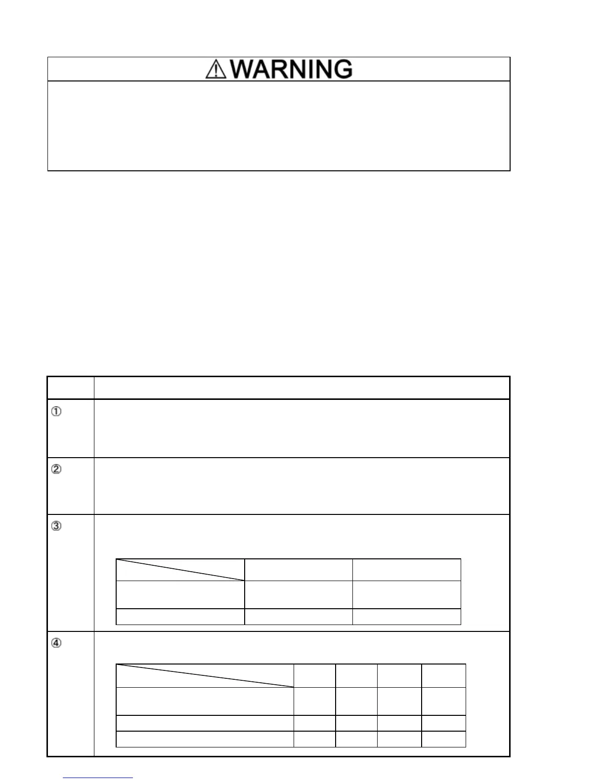
Before changing the switches, turn OFF the power and wait more than five minutes. Make sure
that the LED monitor is turned OFF. Further, make sure, using a circuit tester or a similar
instrument, that the DC link bus voltage between the terminals P (+) and N (-) has dropped below
the safe voltage (+25 VDC).
An electric shock may result if this warning is not heeded as there may be some residual
electric charge in the DC bus capacitor even after the power has been turned OFF.
Switching the slide switches
Switching the slide switches with excessive power, the switches may be damaged.
Switching the slide switches using precision screwdriver, etc. and treat it without damages.
(Do not switching the slide switches with an acute thing such as needles.)
Setting up the slide switches
Switching the slide switches located on the control PCB and interface PCB allows you to customize
the operation mode of the analog output terminals, digital I/O terminals, and communications ports.
The locations of those switches are shown in Figure 2.22.
To access the slide switches, remove the terminal cover and keypad.
For details on how to remove the terminal cover, refer to Section 2.3.1, "Removing the terminal
cover and main circuit terminal block cover."
Table 2.10 lists function of each slide switch.
Table 2.10 Function of Each Slide Switch
Switch Function
SW1
Switches the service mode of the digital input terminals between SINK and SOURCE.
ƒ To make the digital input terminal [X1] to [X5], [FWD] or [REV] serve as a current sink, turn
SW1 to the SINK position.
ƒ To make them serve as a current source, turn SW1 to the SOURCE position.
SW3 Switches the terminating resistor of RS-485 communications port on the inverter on and off.
ƒ To connect a keypad to the inverter, turn SW3 to OFF. (Factory default)
ƒ If the inverter is connected to the RS-485 communications network as a terminating
device, turn SW3 to ON.
SW6
Switches the output mode of the output terminal [FM] between analog voltage and pulse
output.
When changing this switch setting, also change the data of function code F29.
SW6 Data for F29
Analog voltage output
(Factory default)
FMA 0
Current output FMP 2
SW7
SW8
Switches property of the input terminal [C1] for C1, V2, or PTC.
When changing this switch setting, also change the data of function code E59 and H26.
SW7 SW8
Data for
E59
Data for
H26
Analog frequency setting in current
(Factory default)
C1 OFF 0 0
Analog frequency setting in voltage V2 OFF 1 0
PTC thermistor input C1 ON 0 1

 Loading...