5-1
Chapter 5 FUNCTION CODES
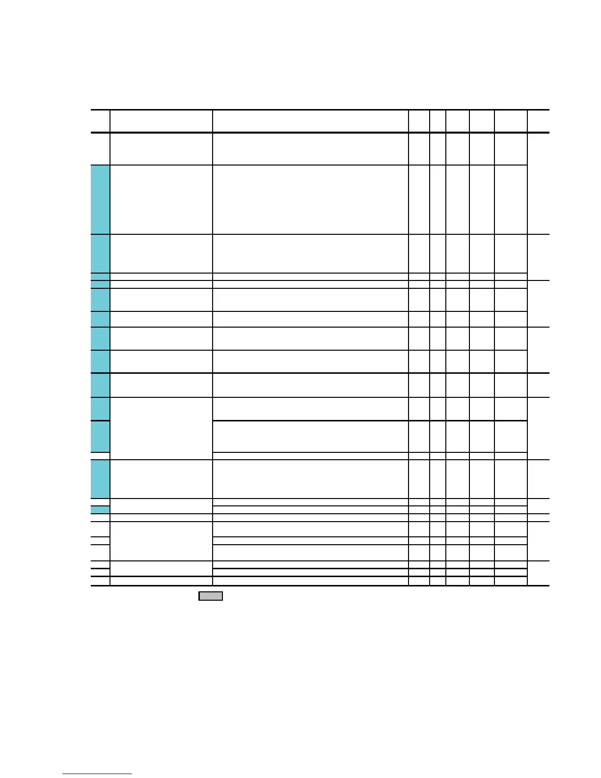
5.1 Function Code Tables
The following tables list the function codes available for the FRENIC-Multi series of inverters.
F codes: Fundamental Functions
Code
Incre-
ment
Unit
Change
when
running
Data
copying
Default
setting
Refer to
page:
F00 0:
㧙㧙
YY 0
1:
2:
3:
F01 0: UP/DOWN keys on keypad
㧙㧙
NY 0
1: Voltage input to terminal [12] (-10 to +10 VDC)
2:
3:
5:
7: Terminal command
UP
/
DOWN
control
11: Digital I/O interface option
12: PG interface card (option)
F02 0: 㧙㧙 NY 2
1: Terminal command
FWD
or
REV
2: RUN/STOP keys on keypad (forward)
3: RUN/STOP keys on keypad (reverse)
F03 25.0 to 400.0 0.1 Hz N Y 60.0
F04 25.0 to 400.0 0.1 Hz N Y 60.0 5-21
F05 0: 1 V N Y2
80 to 240: 230
160 to 500: 460
F06 80 to 240: 1 V N Y2 230
160 to 500: 460
F07 0.00 to 3600 0.01 s Y Y 6.00
F08 0.00 to 3600 0.01 s Y Y 6.00
F09 0.1 % Y Y *4 5-23
F10 1:
㧙㧙
YY 15-25
2:
F11 0.01 A Y Y1
Y2
*4
F12 0.5 to 75.0 0.1 min Y Y 5.0
F14 0: Disable restart (Trip immediately) 㧙㧙 YY 05-28
1: Disable restart (Trip after a recovery from power failure)
4:
5:
F15 Frequency Limiter (High) 0.0 to 400.0 0.1 Hz Y Y 70.0 5-31
F16 (Low) 0.0 to 400.0 0.1 Hz Y Y 0.0
F18 -100.00 to 100.00 *1 0.01 % Y* Y 0.00 5-32
0.0 to 60.0 0.1 Hz Y Y 0.0 5-33
F21 (Braking level) 0 to 100 1% Y Y 0
F22 (Braking time) 0.01 s Y Y 0.00
F23 0.1 to 60.0 0.1 Hz Y Y 0.5 5-34
F24 (Holding time) 0.00 to 10.00 0.01 s Y Y 0.00
F25 0.1 to 60.0 0.1 Hz Y Y 0.2
(Mode selection) Enable restart (Restart at the frequency at which the power failure
occurred, for general loads)
Bias
ޓޓ
(Frequency command 1)
separately powered cooling fan
Enable both data protection and digital reference protection
0.00 : Disable
0.01 to 30.00
0.00: Disable
0.01 to 100.00
1 to 135% of the rated current (allowable continuous drive current) of the
motor
Enable restart (Restart at the starting frequency, for low-inertia load)
0.0 to 20.0
(percentage with respect to "F05: Rated Voltage at Base Frequency 1")
Note: This setting takes effect when F37 = 0, 1, 3, or 4.
Note: Entering 0.00 cancels the acceleration time, requiring external
soft-start.
Note: Entering 0.00 cancels the deceleration time, requiring external
soft-start.
(Thermal time constant)
(Select motor characteristics)
(Overload detection level)
Restart Mode after Momentary Power
Failure
Data Protection
Frequency Command 1
Operation Method
Maximum Frequency 1
Data setting range
Protection for Motor 1 For an inverter-driven motor, non-ventilated motor, or motor with
Disable both data protection and digital reference protection
For a general-purpose motor with shaft-driven cooling fan
Name
Enable data protection and disable digital reference protection
Disable data protection and enable digital reference protection
Current input to terminal [C1] (C1 function) (4 to 20 mA DC)
Sum of voltage and current inputs to terminals [12] and [C1]
(C1 function)
Deceleration Time 1
Rated Voltage at Base Frequency 1
Electronic Thermal Overload
Torque Boost 1
Base Frequency 1
Maximum Output Voltage 1
Acceleration Time 1
Voltage input to terminal [C1] (V2 function) (0 to 10 VDC)
RUN/STOP keys on keypad (Motor rotational direction specified by
terminal command
FWD
/
REV
)
Output a voltage in proportion to input voltage
Output an AVR-controlled voltage (for 230 V class series)
Output an AVR-controlled voltage (for 460 V class series)
Output an AVR-controlled voltage (for 230 V class series)
Output an AVR-controlled voltage (for 460 V class series)
F20
(Braking starting frequency)
Starting Frequency 1
DC Braking 1
Stop Frequency
5-18
5-20
5-22
The shaded function codes ( ) are applicable to the quick setup.
*
1
When you make settings from the keypad, the incremental unit is restricted by the number of digits that the LED monitor can
display.
(Example) If the setting range is from -200.00 to 200.00, the incremental unit is:
"1" for -200 to -100, "0.1" for -99.9 to -10.0 and for 100.0 to 200.0, and "0.01" for -9.99 to -0.01 and for 0.00 to 99.99.
*
4
Default settings for these function codes vary depending on the inverter capacity. See Table 5.1 "Factory Defaults According
to Inverter Capacity" on pages 5-15 and 5-16.

 Loading...