2-28
2.5 Cautions Relating to Harmonic Component, Noise, and Leakage Current
(1) Harmonic component
Input current to an inverter includes a harmonic component, which may affect other loads and power
factor correcting capacitors that are connected to the same power supply as the inverter. If the
harmonic component causes any problems, connect a DC reactor (option) to the inverter. It may also
be necessary to connect an AC reactor to the power factor correcting capacitors.
(2) Noise
If noise generated from the inverter affects other devices, or that generated from peripheral
equipment causes the inverter to malfunction, follow the basic measures outlined below.
1) If noise generated from the inverter affects the other devices through power wires or grounding
wires:
- Isolate the grounded metal frames of the inverter from those of the other devices.
- Connect a noise filter to the inverter power wires.
- Isolate the power system of the other devises from that of the inverter with an insulated
transformer.
2) If induction or radio noise generated from the inverter affects other devices through power wires
or grounding wires:
- Isolate the main circuit wires from the control circuit wires and other device wires.
- Put the main circuit wires through a metal conduit pipe, and connect the pipe to the ground
near the inverter.
- Install the inverter into the metal switchboard and connect the whole board to the ground.
- Connect a noise filter to the inverter power wires.
3) When implementing measures against noise generated from peripheral equipment:
- For the control signal wires, use twisted or shielded-twisted wires. When using
shielded-twisted wires, connect the shield of the shielded wires to the common terminals of
the control circuit or ground.
- Connect a surge absorber in parallel with magnetic contactor's coils or other solenoids (if any).
(3) Leakage current
A high frequency current component generated by insulated gate bipolar transistors (IGBTs)
switching ON/OFF inside the inverter becomes leakage current through stray capacitance of inverter
input and output wires or a motor. If any of the problems listed below occur, take an appropriate
measure against them.
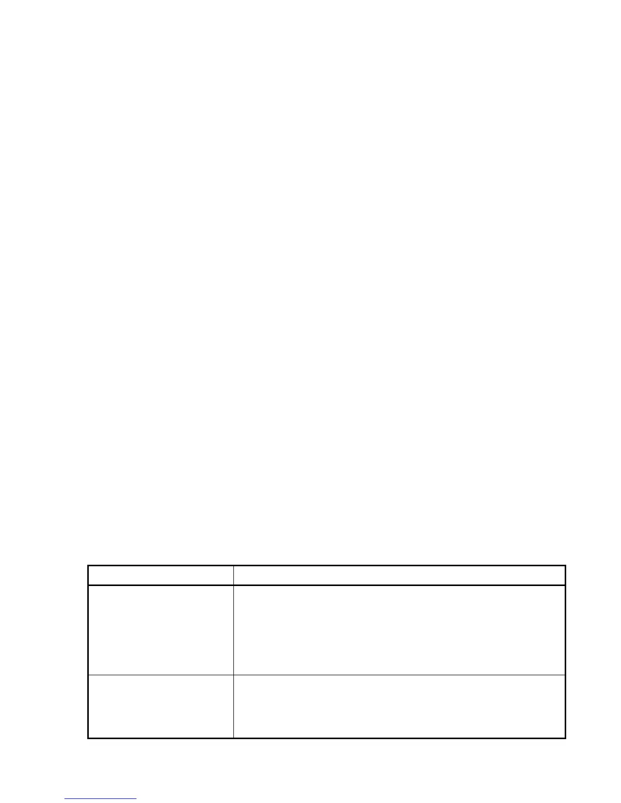
Table 2.11 Leakage Current Countermeasures
Problem Measures
A residual-current-operated
protective device (RCD) or a
ground fault circuit
interrupter (GFCI) that is
connected to the input
(primary) side has tripped.
1) Decrease the carrier frequency.
2) Make the wires between the inverter and motor shorter.
3) Use an RCD or GFCI with lower sensitivity than the one currently
used.
4) Use an RCD or GFCI that features measures against the high
frequency current component (Fuji SG and EG series).
An external thermal relay
was activated.
1) Decrease the carrier frequency.
2) Increase the settling current of the thermal relay.
3) Use the electronic thermal overload protection built in the inverter,
instead of the external thermal relay.

 Loading...