2-1
2. WIRING
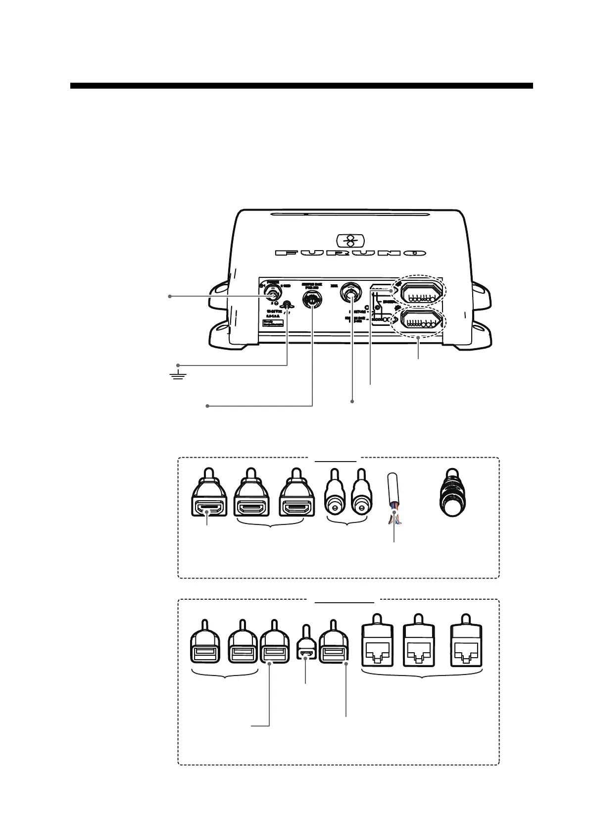
2.1 Interface Connections Overview
The figure below shows the connections available on the processor unit. For detailed
information on connections, see the interconnection diagram at the back of this man-
ual.
Ground wire
IV-8sq.
Transducer
QZF-H032+
To Switch
Box
To ship’s
ground
Top layer (see below for details)
Top layer (see below for details)
Bottom layer
(see below for details)
Bottom layer
(see below for details)
Top layer
Bottom Layer
VIDEO IN 1/2
MULTI cable
For external buzzer,
autopilot, etc.
HDMI IN HDMI OUT 1/2
For touch
monitors
NMEA 2000
USB for
touch
monitors
USB for
SWITCH BOX
USB2
For
external
HDD*
USB1
For MCU-002/004
*: Also used to output touch commands to external equipment.
NETWORK1/2/3
For network connections
(HUB-101, etc.)
MJ-A3SPF0019-035C
To ship’s mains
(12 to 24 V DC)
 Loading...