2. WIRING
2-6
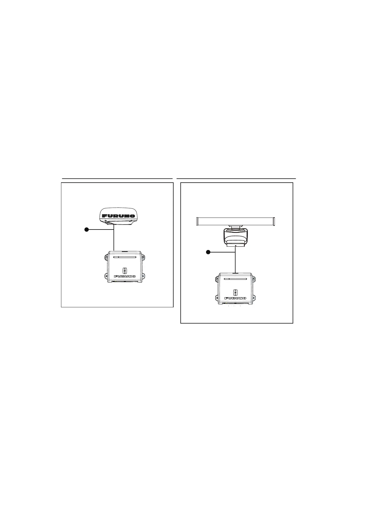
2.4 DRS Radar Sensor Connections
Depending on your configuration, a separate power supply may be required for you
radar sensor.
The figures below show connection examples with radar sensors which are compati-
ble with the TZT2BB.
For details regarding connection and cables required for connection with the radar
sensor, see the radar sensor’s installation manual.
Note 1: DRS2D-NXT and DRS4D-NXT cannot be used in Japan.
DRS4D X-Class is for Japanese market only.
Note 2: The Ethernet hub HUB-101 (available as an optional extra) is required for con-
figurations comprising DRS4DL, DRS4DL+, DRS4D NXT, DRS6A X-Class, DRS6A
NXT, DRS12A X-Class or DRS25A X-Class, and networked with sensors via LAN.
2.5 Network Connection with Other TZT Series Units
Your TZT2BB is equipped with three network connectors (RJ45). Like previous
NavNet series equipment, the TZT2BB is able to share Radar images and other infor-
mation, across an Ethernet connection. Up to four NavNet TZtouch units may be con-
nected to the same network at one time (see page iii for the details). For example, a
configuration with one TZT22X and one TZT12F can have two TZT2BB units connect-
ed.
Connection example for radome sensors
DRS4DL+, DRS4D X-Class
DRS2D-NXT, DRS4D-NXT
Processor Unit
MPU-004
Connection example for open-array sensors
DRS6A X-Class, DRS12A X-Class,
DRS25A X-Class, DRS6A-NXT,
DRS12A-NXT, DRS25A-NXT
To ship mains
(12 to 24 VDC)
Processor Unit
MPU-004
To ship mains
(12 to 24 VDC)
 Loading...