Modifications reserved Page 28/99
OPM_SPE_XXX_10K_40K_8GB_V020.doc Operating Manual SitePro 10-15-20-30-40 kVA / S8
5.7 ELECTRICAL WIRING
WARNING !
UPS installation and connection must be performed by QUALIFIED SERVICE
PERSONNEL only.
Refer to the “Safety prescriptions - Installation” described on Section 1.
5.7.1 Mains input connection
Ensure that the AC and DC external isolators are OFF, and prevent their inadverted operation.
Do not apply power to the equipment prior to the commissioning by a qualified engineer.
Before any other input connection, connect and check the PE wire.
The mains input power connection can be common or separate for bypass supply and rectifier input,
depending on the electrical system provided by the customer.
Common input Rectifier & Bypass
The same power source is to be used for both bypass supply and rectifier input (input F3).
Bear in mind that when the mains fuses are opened there is a supply failure to the rectifier as well as
to the bypass and manual bypass switch.
In this case, the interconnection links BR1, BR2 and BR3 on the input terminals MUST
REMAIN CONNECTED.
Separate input Rectifier & Bypass (recommended)
The bypass and rectifier use different power sources (F1 and F2 inputs).
In this case, when the rectifier-input fuses are opened, the automatic bypass and the manual bypass
are supplied by the other connection.
In this case, REMOVE the interconnection links BR1, BR2 and BR3 on the input terminals
or bus bars. See Fig. 5.8.1-1.
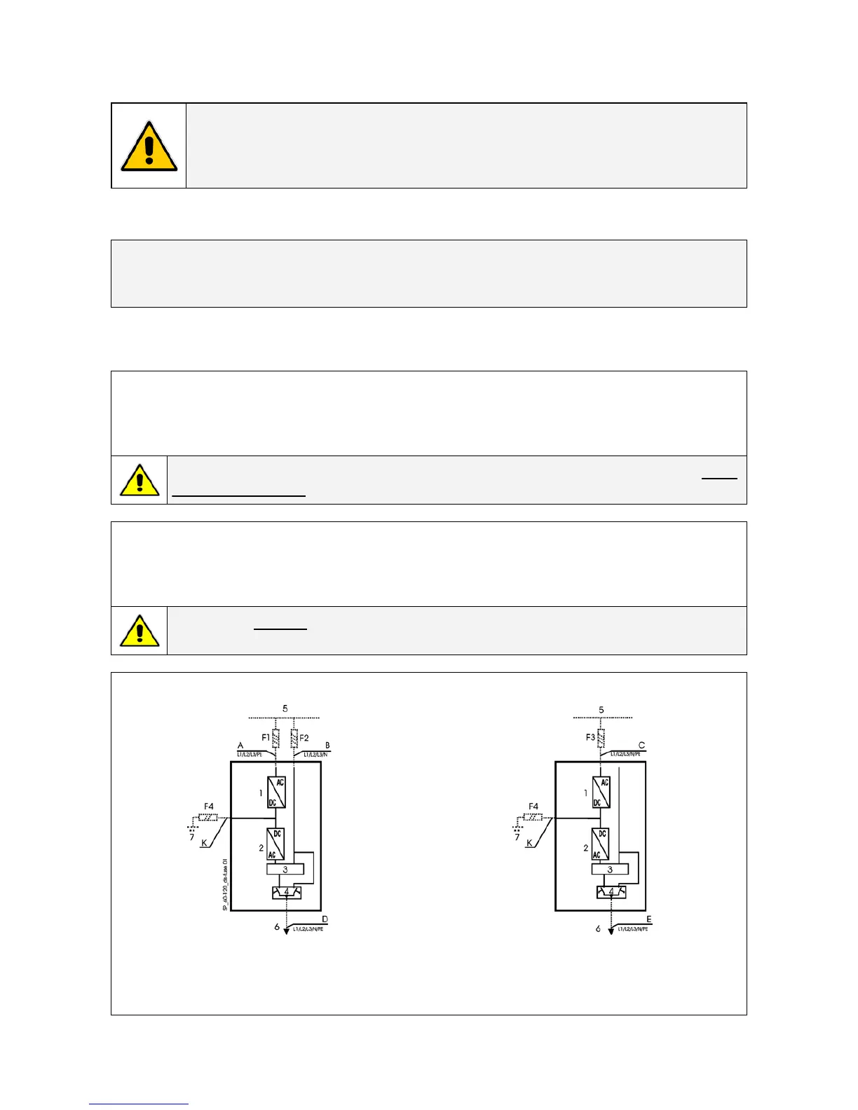
Separate input Rectifier & Bypass Common input Rectifier & Bypass
Fig. 5.7.1-1 Separate input rectifier & bypass Fig. 5.7.1-2 Common input rectifier & bypass
1 = Rectifier
2 = Inverter
3 = Automatic bypass
4 = Manual bypass
5 = Mains input
6 = Load
7 = Battery
 Loading...