Modifications reserved Page 49/99
OPM_SPE_XXX_10K_40K_8GB_V020.doc Operating Manual SitePro 10-15-20-30-40 kVA / S8
7.3.1 Events (alarms and messages)
Each of the following listed events, alarm or message, can be displayed on the LCD screen, on a PC with
the software “GE Data Protection” installed or with the monitoring system “GE Power Diagnostic”.
Alarms and Messages are differently specified because the alarms are indicating an abnormal
functioning of the UPS (which are additionally signalled with the LED alarm and acoustically with the
buzzer), while the messages indicate the various states of operation of the UPS (stored in the events list,
but not activating the LED alarm and the acoustical alarm).
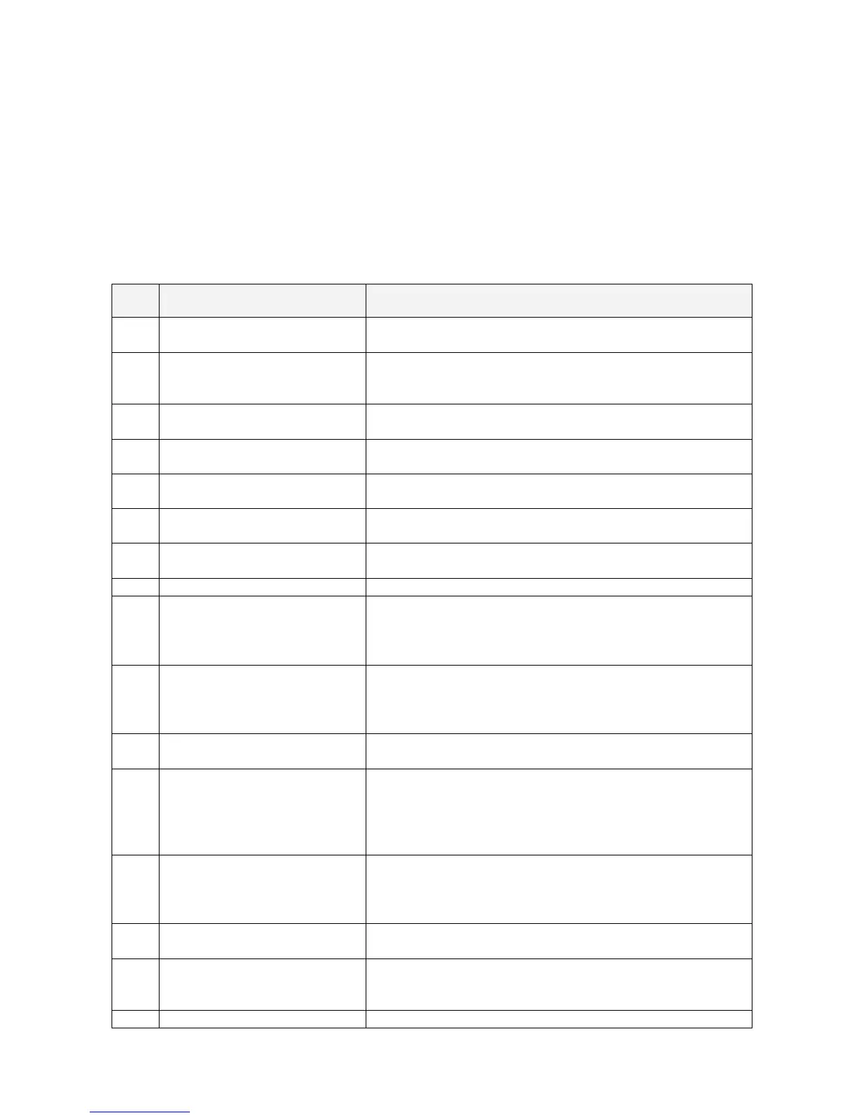
7.3.2 Alarms list
Code Alarms Meaning
4000
SETUP VALUES LOST
Parameters are lost and have been replaced with default
values.
4001
REGULATION BOARD FAILURE
A blocked DSP on the Control board causes this alarm, and
consequently the shutdown of rectifier and inverter and the
opening of K3.
4004
UPS FAILURE
ON PARALLEL SYSTEM
The master unit detected the slave unit missing on the
communication bus even though switch Q1 is still closed.
4006
BUS JA CRC FAILURE
The parallel communication bus system is subject to high
errors rate on channel JA.
4007
BUS JB CRC FAILURE
The parallel communication bus system is subject to high
errors rate on channel JB.
4008
BUS JA FAILURE
There is an interruption in the channel JA of the parallel
communication bus system.
4009
BUS JB FAILURE
There is an interruption in the channel JB of the parallel
communication bus system.
4010
CONNECTIVITY BUS FAILURE The connectivity communication bus is faulty or interrupted.
4104
BATTERY FUSES FAILURE
This function, when enabled on input programmable relays
(password required), warns the user about the external
battery fuses failure or MCB opening, signalled by NO free
contact.
4106
RECTIFIER TRANSFORMER
OVERTEMPERATURE
The temperature sensor inside the input transformer
winding indicates overtemperature. Only the alarm is given.
The rectifier, when in an Off state, cannot start as long as
this condition persists.
4110
RECTIFIER MAINS OUT
OF TOLERANCE
Rectifier input mains is out of tolerance (voltage, frequency
or phase).
4115
LOW BATTERY VOLTAGE
The battery has been discharged and reached “stop
operation” time-out (default 3 minutes), and the inverter will
be shut down.
It will restart automatically only when the battery has
recharged enough for a minimum runtime.
4116
HIGH BATTERY VOLTAGE
Dangerous high UDC-Voltage.
Causes inverter shutdown.
Inverter restarts automatically after battery returns to
normal floating voltage.
4117
BATTERY EARTH FAULT
A leakage current to earth has been detected on the DC
circuit.
4118
BATTERY FAULT
During battery test the voltage falls under the critical level
(depending setting parameters).
Battery test is stopped.
4121
HIGH DC RIPPLE A high ripple is present in the battery voltage.
 Loading...