Modifications reserved Page 86/99
OPM_SPE_XXX_10K_40K_8GB_V020.doc Operating Manual SitePro 10-15-20-30-40 kVA / S8
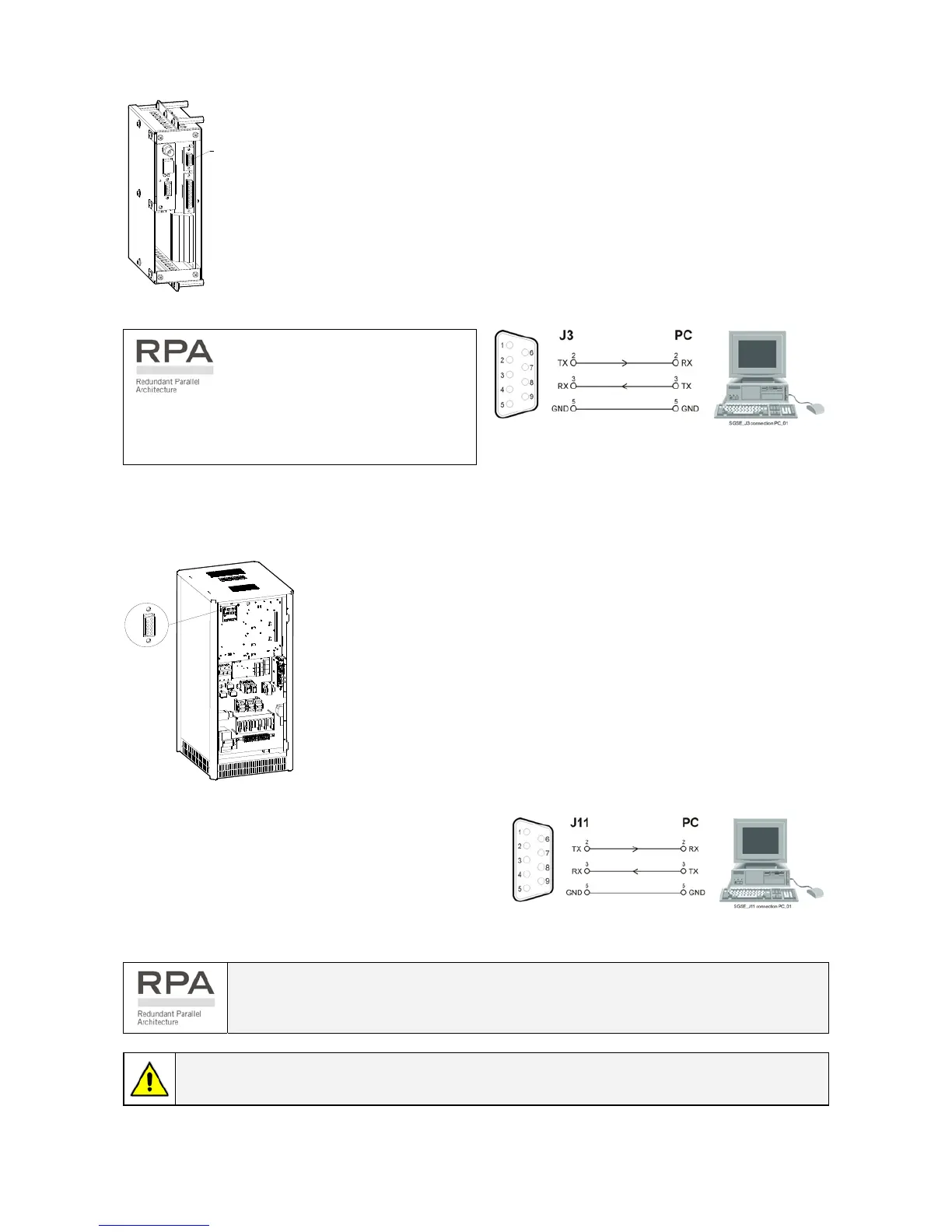
9.1.1 Serial Port J3 - RS232 (sub D, female 9 pin)
SP_010-04 0_S7_J3_01
J3
Fig. 9.1.1-1 Serial port J3
Total remote management of the system using software GE Power
Diagnostics, GE Data Protection or GE Service Software for system
protection and management of the UPS systems.
The serial port J3 - RS232 is enabled on all the
units of the Parallel System.
Fig. 9.1.1-1 Serial port J3 connection to PC with RS232 1:1
cable DB9m – DB9f
9.1.2 Serial Port J11 - RS232 (sub D, female 9 pin) - Option
S
P
_
0
1
0
-
0
4
0
_
S
7
_
J
1
1
_
0
1
J11
Fig. 9.1.2-1 Serial port J11
Total remote management of the system on PC by means of the
ARGUS - Control Network Software (optional).
This software enables the user to monitor the status of remote UPS
from any computer connected to a modem, or through a direct link to
the UPS.
Connection of a serial printer
From the display panel it is possible to select
printing of measurements, alarms and parameters
(see Section 7.4 – SETUP / PRINT).
Fig. 9.1.2-2 Serial port J11 connection to PC with RS232
1:1 cable DB9m – DB9f
The serial port J11 - RS232 is enabled only one unit of the Parallel System
(normally unit no. 1).
Do not use the serial port J11 on the other units of the same Parallel System.
NOTE !
Communication on J11 port is enabled also in case the J3 connector is already connected.
 Loading...