Modifications reserved Page 69/99
OPM_SPE_XXX_10K_40K_8GB_V020.doc Operating Manual SitePro 10-15-20-30-40 kVA / S8
8.1.3 From Manual Bypass Q2 to normal function VFI.
NOTE !
UPS system has been turned OFF following the “Maintenance shutdown (Load on Q2)”
procedure and the load is still powered by manual bypass Q2.
The load must be transferred back to the UPS system.
Open the front door and make sure that:
• The safety screens are fixed in their position.
• The switches Q1 and Q4 are open (Pos. O), and the battery fuses F8 – F9 are disconnected.
The switch Q2 must be closed (Pos. I).
• LED Alarm is lit.
The synoptic diagram must display the status “LOAD
SUPPLIED BY MANUAL BYPASS Q2”.
1. If not already supplied (separate mains inputs), switch-ON the mains power to the rectifier
input.
2.
Close the input rectifier switch Q4 (Pos. I).
LED 1 (input mains rectifier) must be lit and LED 3 (rectifier) must blink.
The rectifier starts up automatically, supplying the DC circuit, and charging the DC capacitors.
The LED 3 (rectifier) stops blinking and stays ON, indicating that the DC link has reached the floating voltage.
3.
Battery coupling to DC link.
After awhile, the green LED LD1 next to the battery fuse carrier, F8 – F9 lights up, indicating the rectifier
supplies the floating voltage.
After checking the right polarity, connect the battery to the DC-link by closing F8 – F9.
The battery is now connected to the DC link. LED 4b (charging battery) should be lit indicating battery charge.
4. Close the output switch Q1 (Pos. I).
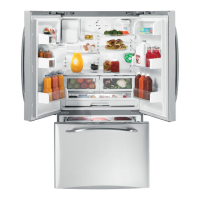
Load is now supplied parallel through automatic bypass and
manual bypass Q2.
Attention: before executing next procedure 5 ensure that
The synoptic diagram must display the status “LOAD
SUPPLIED BY AUTOMATIC BYPASS AND MANUAL BYPASS
Q2”.
5. Open the manual bypass switch Q2 (Pos. 0).
LED 9 (manual bypass Q2) is Off.
The load is supplied by the mains through the automatic bypass.
6.
Insert the inverter by pressing “Inverter ON” ( I ) key.
The inverter will start up. LED Inverter (5) must be blinking.
In a short time, when the inverter voltage is confirmed, the LED Inverter (5) will stop blinking and stay fixed
lit.
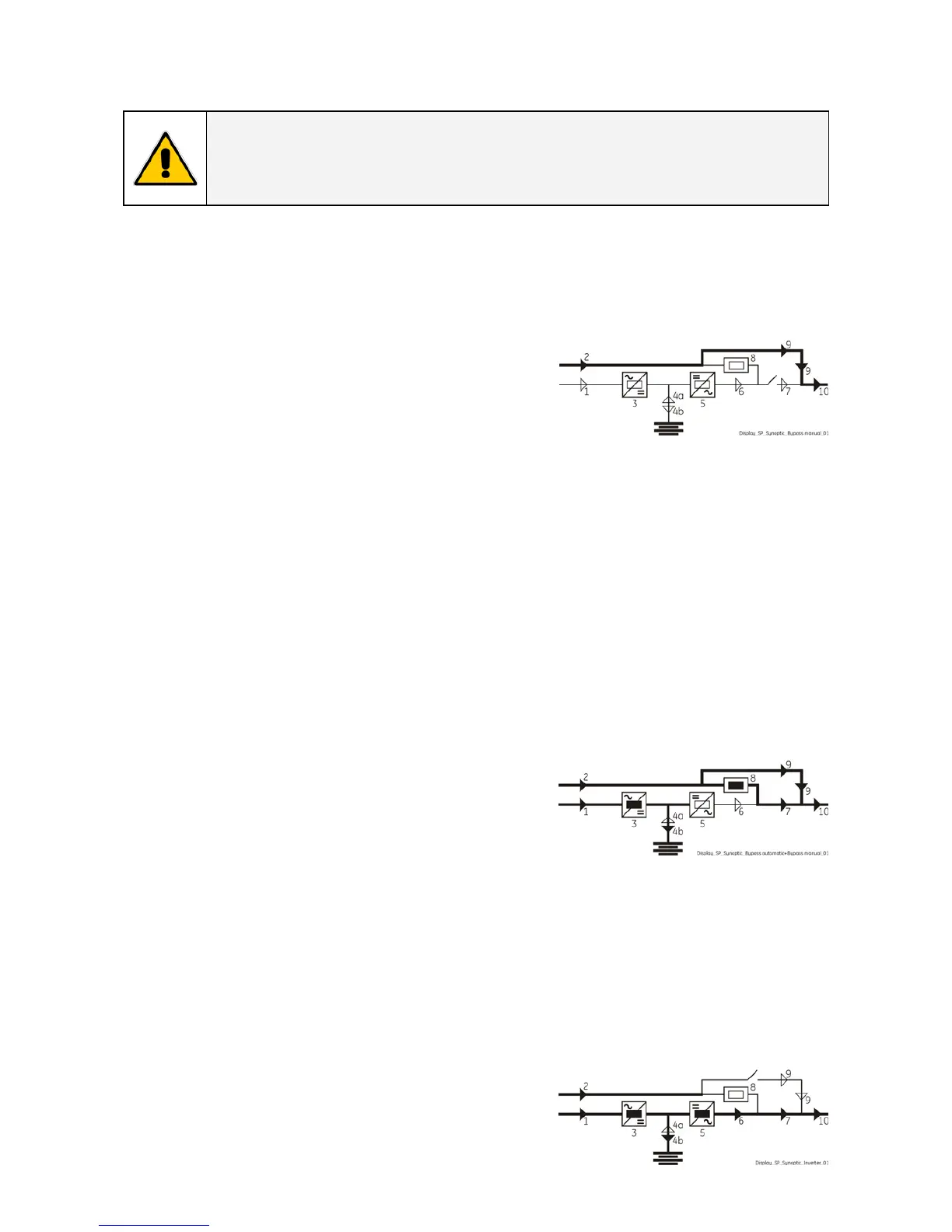
The load will be automatically transferred from mains to inverter.
LED Alarm turn Off and the LED Operation must be lit.
The synoptic diagram must display the status “LOAD
SUPPLIED BY INVERTER”.
 Loading...