Modifications reserved Page 39/99
OPM_SPE_XXX_10K_40K_8GB_V020.doc Operating Manual SitePro 10-15-20-30-40 kVA / S8
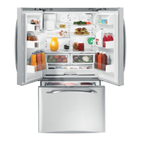
5.9.3 Control bus cable location
SP_010-040_S6_RPA control bus location_01
Fig. 5.9.3-1 View electronic module
Access to the control bus connection.
The control bus connection between
parallel units must be made on the front
of the electronic module fitted behind the
front door
SP_010-300_S6_RPA-IM0048_04GB
P
3
P
1
3
N
e
xt
p
a
r
a
l
l
e
l
u
n
i
t
JA
JA-2
JA-1
JB-1
JB-2
F
JB
J52(A)
J62(B)
F
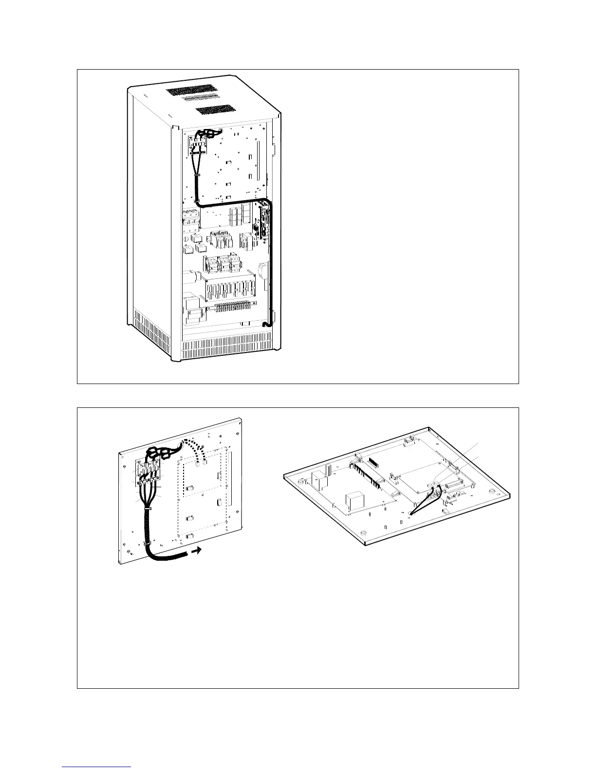
Fig. 5.9.3-2 Front view electronic module on intermediate unit
P1
1
J62 (B)
S
P
_
01
0
-
0
4
0
_S
7_
RP
A
-
I
M
0
0
4
8
_0
2
J52 (A)
P
13
P
2
P
3
Fig. 5.9.3-3 Internal view electronic module
Control bus cables connection.
• Plug the cables JA (1/2/3/4/5/6/7) and JB (1/2/3/4/5/6/7) onto the RJ connectors JA and JB
located on parallel bus PCB P34 – Bus Interface (IM0048) (going to P13 – RPA Board J52 and J62).
• Fix both cables JA (1/2/3/4/5/6/7) and JB (1/2/3/4/5/6/7) to parallel bus socket connecting the
cable shield to ground by means the cable clamps “F“.
 Loading...