Modifications reserved Page 95/99
OPM_SPE_XXX_10K_40K_8GB_V020.doc Operating Manual SitePro 10-15-20-30-40 kVA / S8
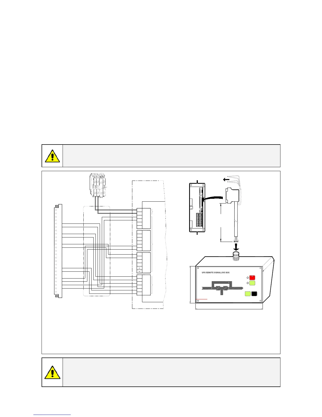
10.5.3 Remote Signalling Box (RSB)
The optional Remote Signalling Box allows monitoring of the operation of the UPS, using the potential
free contacts fitted on the “P4 - Customer Interface Board“ of the UPS.
It can be used by simply putting the box on a desktop or on a wall or, removing the box, it can be
surface mounted.
The remote panel contains an internal buzzer and the following status indicators:
• Mimic diagram With LEDs indicating the operation of Rectifier and Inverter, and the power source
supplying the critical Load.
• Alarm Indicating a critical situation on the UPS (LED light and audible alarm).
• Stop Indicating the UPS is preparing to shut down in a short time.
• Mute Push key, resets the buzzer.
• Test Push key checks all the LEDs and the buzzer of the remote panel.
The cable connecting the RSB to the UPS cabinet must be min. 16 wires / 0.25mm
2
.
The plug B is included in the delivery of the option RSB (cable connecting UPS with RSB not included).
Maximal allowable length: 300 m (985 ft).
It must be wired at one end with a D - female plug- 25 pin (J2 – P4 Customer Interface Board).
NOTE !
The alarms on free potential contacts can be connected on terminals X1 instead J2 (see
correlation X1 – J2 in Section 9.1).
XY 16 x 0,25mm
CABLE TYPE
max 300m / 985ft
1
2
4
3
5
7
6
8
10
9
11
13
12
14
16
15
17
20
22
23
19
18
21
24
16
20
22
23
17
19
38
56
55
50
43
44
49
40
42
SIGNALLING
GND
24V
34
37
33
32
31
X15
IM6544
1
2
J2 - SUB D - MALE
REMOTE
X3
X4
A
A
B -
P4 - Customer Interface
B
PLUG
J2
SP_OPT_010-040_S7_RSB_01GB
25
XB
C
TERMINALS
TERMINALS
C
XB
J2
pink
red
SUB D - MALE
2" in
216mm
5 1/4" in
130mm
GE Digital Energy
g
TestMute
Alarm
Stop
77mm
3
i
n
J4
J5
1
1
9
14
1
2
8
19 2 1 2220
10 119
17 181615
7654
12 1 413
321
J3
JP3
X2
X1
_
+
L
N
XB2
XB1
F50
XB3
grey + blue
pink + red
yellow/brown
white/yellow
brown/green
white/green
blue/red
violet
grey/pink
yellow
green
brown
white
COMMON ALLARM
AUX. BUZZER
STOP OPERATION
LOAD ON MAINS
LOAD ON INVERTER
UTILITY FAILURE
black
P.S.: The above mentioned colors are
suitables only for XY standard cable
BLOCK
BLOCK
Only for SitePro 30-40kVA
grey
blue
_
Fig. 10.5.3-1 Remote Signalling Box connection
A
Terminals X3, X4 and X15 fitted inside the Remote Signalling Box.
B
Plug J2 (sub D - male - 25 pin) must be connected to the connector J2 (sub D - female-25
pin) located on “P4 - Customer Interface Board“.
C
Terminals block XB for 24 Vdc supply Remote Signalling Box.
NOTE !
If the remote signal panel is plugged on connector J2, the terminal blocks X1 cannot be
used to drive an external alarms monitoring device, because it is supplied by the
internal UPS low voltage power supply.
 Loading...