Modifications reserved Page 88/99
OPM_SPE_XXX_10K_40K_8GB_V020.doc Operating Manual SitePro 10-15-20-30-40 kVA / S8
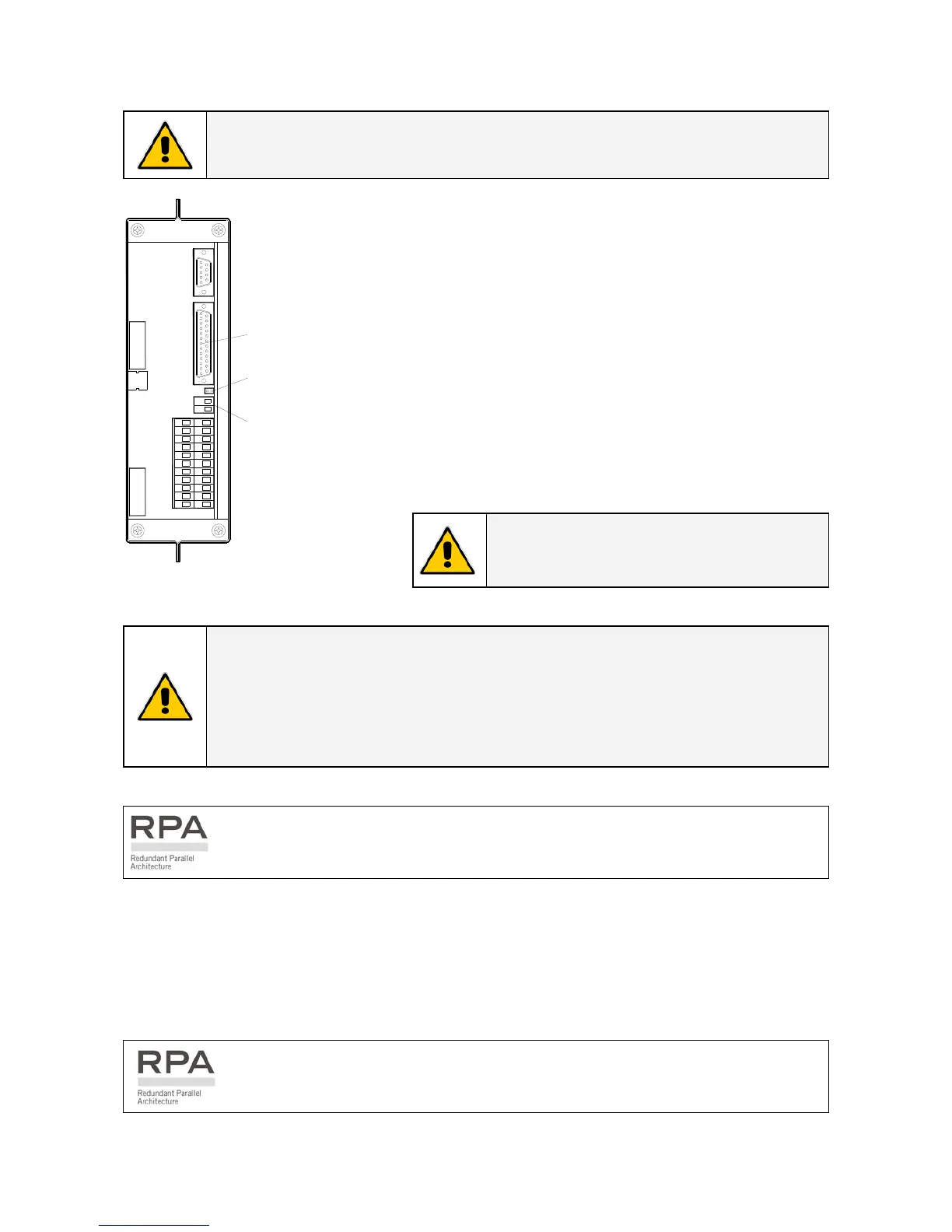
9.1.5 EPO (Emergency Power Off)
Be aware:
The reliability of the system depends on this contact NC (Normally Closed)!
An external Emergency switch (Normally Closed voltage-
free contact) can be connected on terminals X2 / 1, 2 or
connector J2 / 12, 25 of the P4 - Interface Customer.
Remove the cable short-circuiting terminals X2 when using
this external switch.
When opened, this contact causes the immediate opening
of the Contactors K6 and K7, as well as the shutdown of
Rectifier, Inverter and Static-Switch.
SP_010-040_S7_X2-EPO_01
J4
J5
1
1
9
14
1
2
8
19 21 2220
10 119
17 181615
7654
12 1413
321
J3
J2
JP3
X2
X1
J2
JP3
X2
Fig. 9.1.5-1 X2 and J2 for connection EPO
NOTE !
This procedure could imply a load shutdown.
NOTE !
To enable this function, remove jumper JP3 on the P4 - Customer Interface, when the
cables have already been connected on X2 or J2.
In case of parallel Customer Interface the EPO contact must be connected to one
Customer Interface only, but the bridge on X2 and jumper JP3 on the P4 – Customer
Interface must be removed on all other boards.
In a Parallel System a separate NC (Normally Closed) contact must be connected
individually to each unit.
When the EPO has been activated, the system must be restored as follows:
• Press the push-button EPO (contact on X2 / 1, 2 is closed again).
• Press the key “O” (Inverter OFF – see Section 6.2) on the control panel.
• Press the key “I” (Inverter ON – see Section 6.2) on the control panel.
In case of a Parallel System press the key “O” (Inverter OFF) on the control panel of
each unit connected on the parallel bus and having its output switch Q1 closed.
 Loading...