Modifications reserved Page 93/99
OPM_SPE_XXX_10K_40K_8GB_V020.doc Operating Manual SitePro 10-15-20-30-40 kVA / S8
10.5 CONNECTION FOR OPTIONS
WARNING !
The installation and cabling of the options must be performed by QUALIFIED
SERVICE PERSONNEL only.
MAKE SURE THAT THE UPS INSTALLATION IS COMPLETELY POWERED DOWN.
Refer to the “Safety prescriptions - Installation” described on Section 1.
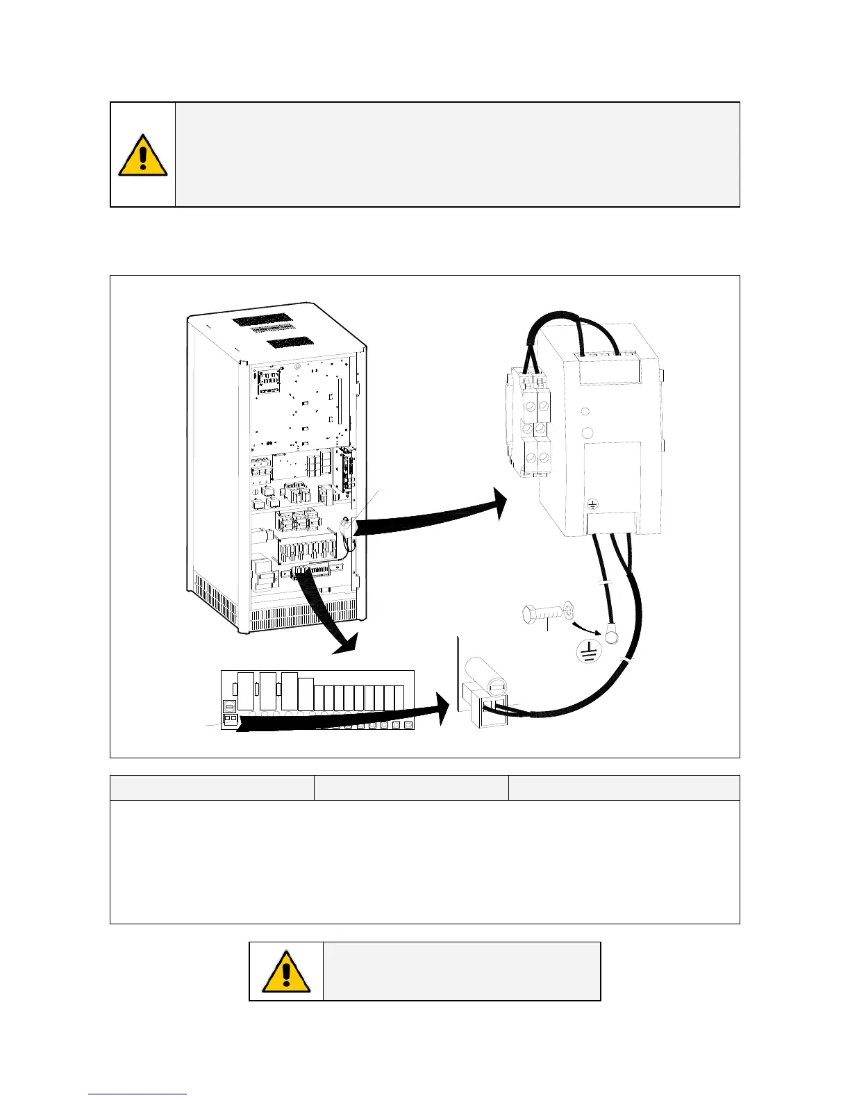
10.5.1 Auxiliary Power Supply (APS) 24 Vdc for SitePro 10 - 15 – 20 kVA
PA = Auxiliary Power Supply 24 Vdc XA = Terminals for connection 230 VAC XB = Terminals for connection 24 Vdc
L1
N
PA
OPT_APS_SP010-020 S7_01
L
N
XB
N
C
-
-
+
+
PA
_
+
XB1
XB2
F50
M4x10
P29 - IM0062 Interface Suppressor
XA
F50
XA
Fig. 10.5.1-1 Auxiliary Power Supply 24 Vdc for SitePro 10 – 15 – 20 kVA
Connection From To
Cable PA+ (black) PA - APS: PA+ Terminal: XB1 (+)
Cable PA- (grey) PA - APS: PA- Terminal: XB2 (-)
Cable PA-L (black) PA - APS: L Terminal: XA-L1
Cable PA-N (grey) PA - APS: N Terminal: XA-N
Cable PA-PE (yellow-green) PA - APS: PE UPS frame: PE (see Fig. 10.5.1-1)
NOTE !
Clamp the cables with the cable-ties.
 Loading...