OUTDOOR TECHNICAL OVERVIEW
ENGLISH
B-4
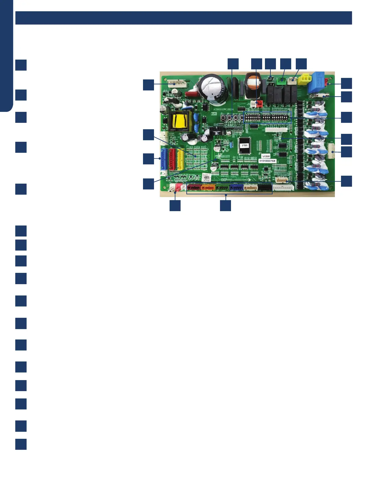
Components
Voltage to operate the PCB is provided
by the Power Filter Board on terminals
ACN and ACL.
When power is present, the Green LED
will light.
The communication cables to the PCB
from the Power Filter Board connect to
CN6 and CN34.
The Service Monitor Board connects
to plugs CN-23 and CN-8. When these
cables are connected to the Service
Monitor Board, the SMB digital display
should be illuminated.
Plug CN-21 connects the data path
between each indoor unit and the PCB .
The connections from this plug terminate
at the Number 3/C terminal at the indoor
unit voltage connection terminal strips.
The Outdoor Fan Motor is a DC voltage, variable speed type that connects to the PCB at terminal Plug CN-11.
The 4-Way Valve is energized by line voltage from a connection via Plug CN-5. This valve is energized in HEAT MODE.
The Crankcase Heater is energized via a connection at terminals CON-9 and CON-8 on the PCB.
The EEV coils for the outdoor unit and each indoor unit are connected at terminals CN-15 through CN-18. These EEV coils
include the connection for the HEAT MODE EEV coil.
There are a set of temperature sensors that monitor the temperature of the refrigerant entering and leaving each circuit.
These sensors are mounted in a group near the center of the circuit board.
There are system temperature sensors that monitor refrigerant line temperature and outdoor air temperatures. These
sensors plug into the PCB via Plugs CN-14, CN-1, CN-7, and CN-24.
The system has two refrigerant pressure switches, a Low Pressure Switch and a High Pressure Switch. These switches are
connected to the PCB via Plugs CN-12(HP) and CN-13(LP).
There are three sets of DIP switches. SW5 and SW7 aect the operational parameters of the unit. Refer to the wiring
diagram for the correct settings. SW6 positions are changed only when a Central Controller is used.
There are 4 surface mounted buttons located next to SW-5 and SW-6. These buttons are for factory use only.
The PCB has a Green LED and a Red LED. When power is present, the Red LED is on. When two or three indoor units are
connected, the Green LED is on.
T5A 250V rated ceramic fuse is located on the PCB. This fuse will open if excessive current occurs or if a power surge is
present. This fuse is eld replaceable.
Base pan heater connection (150W).
2
10
6
4
12
8
7
3
11
9
5
13
14
15
16
17
1
The PCB is connected via communication cables to the Inverter Power Module, Filter Board, and the Service Monitor Board.
1
14 3 8 17 7
16
13
15
5
4
912
6
10
11
2
PCB
 Loading...