WALL MOUNT TECHNICAL OVERVIEW
ENGLISH
C-2
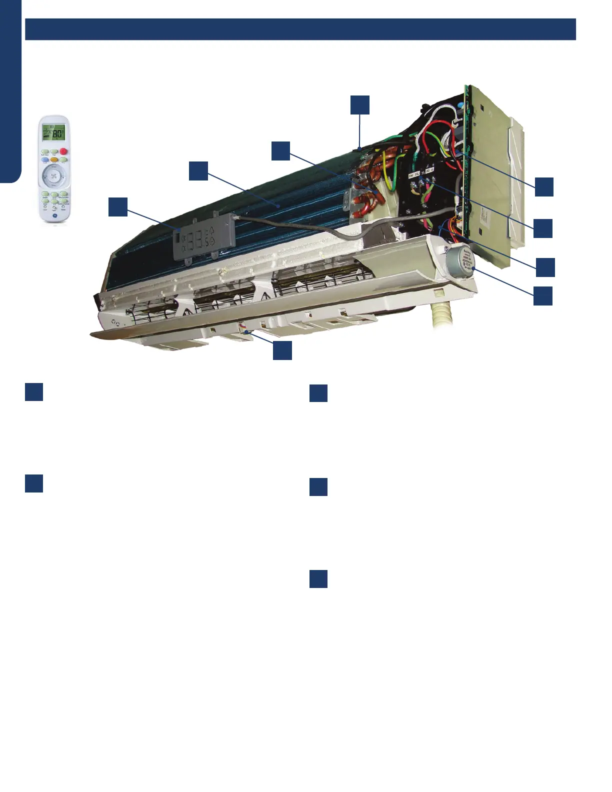
Components
Terminal Block
Power to operate the indoor unit comes from the
electrical line voltage terminal block at the outdoor unit.
The wiring includes 4 wires: 1, 2, 3 and ground. Wires 1
and 3 complete the data path. These wires should always
be 14 gauge AWG Stranded type wire. Splices in wires 1
or 3 may cause communication errors.
Blower Assembly
The blower assembly consists of a plastic blower wheel
that is connected to a variable speed indoor blower
motor. A set screw holds the blower wheel to the blower
motor.
The indoor blower motor is a DC Fan Motor that is
connected to the indoor unit control board. The wiring
from the motor to indoor board consists of 5 wires
connected to pins 1, 4, 5, 6 and 7. Pin 1 should have 310
VDC. Pin 4 is ground. Pin 5 +15VDC. Pin 6 is the feedback
signal. Pin 7 is the speed control.
During normal operation, the indoor control board will
energize the indoor blower motor and request proper
speed. The indoor blower motor will control the speed
via a command at the Pin 7 speed control. Proper fan
speed is veried by the indoor control board via the
voltage level at the feedback signal on Pin 6. Should
the feedback signal not be present during a call for
indoor blower, the indoor control board will indicate a
Malfunction Code E14.
Louver Stepper Motors
Separate motors located in the indoor unit control the
operation of the motorized louvers. All of the louver
motors are controlled via commands received from the
remote control. The blower motor is controlled by both
the remote control and by commands from the outdoor
unit ECU.
Pipe Temperature Sensor
The Piping Temperature Sensor senses indoor coil
temperature in the cooling mode and in the heating
mode. This sensor is used for Anti Freezing and Anti
Cold Blow cycles. The sensor also provides critical
temperature information to the ECU that may be used in
frequency adjustments.
Ambient Temperature Sensor
The ambient air sensor senses the temperature of
the air being drawn into the wall mounted unit from
the conditioned space. This sensor provides room
temperature information to the ECU for calculation of
inverter capacity and temperature control.
2
4
6
8
1
3
3
5
7
The wall mounted units act as evaporator coils during cooling mode and condenser coils during heating mode. These units have
gravity condensate drain systems. If a condensate pump is needed, it must be eld provided and mounted external to the indoor
unit.
1
2
3
4
5
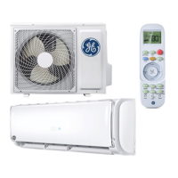
The wall mount unit is shipped
with a wireless controller.
Component Overview
 Loading...